I just need to think of a way to properly test the DC detection now. I think it will involve removing the output inductor and resistor to apply DC.
Good!My new NS-OPS boards with built in DC detection fired right up and work perfectly. Next they go into a chassis and get some proper testing.
On board solid state protection is an interesting and very comfortable option.
I just need to think of a way to properly test the DC detection now. I think it will involve removing the output inductor and resistor to apply DC.
Jeff, as an option for the future update - we can add a service connector "DC Test" - see attached.
In this case, we can apply the test signal - AC, DC, AC + DC - whatever it is through the circuit shown, even when the amplifier is up and running, without interfering with it - just using an independent "parallel" channel.
Attachments

Or just have the whole circuit on the board and connector for DC Test Signal 🙂
Jumpered to ground when not in use.
Jumpered to ground when not in use.
My concern is that we need to apply DC to the output from the amp to test it. Disconnecting R1 from the output and applying voltage there would work for testing. A simple solder blob jumper between it and Q8 would work for this. I'd like to add a bunch of test points for measuring and applying test voltages in the next round.
There is DFM and then there is DFT, all part of learning to design.
That is why for pro design, we have design reviews, so that everyone involved down the line, gets their say.
Then there is design verification. Nothing wrong with removing or partially stuffing comps in order to verify a design.
For instance, when I get in a new design, that incorporates a power supply, I always stuff the P/S first, to verify that it works properly. Nothing worse than fully stuffing a new pcb and the P/S smokes all or some of the comps. Tough lesson to learn and embarrassing to boot, esp. if the boss is watching in anticipation.
Brought to you by the "School of hard knocks" 🙂
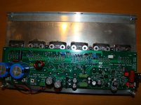
Well...I guess i was overdue. Had an amp go south. Thankfully the protection circuit seems to have saved the ribbon tweeter.
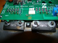
Playing at low volume and there is a "snap" sound and a bit of a smell. See the black stains around the two bolts holding the output transistors Q23 and 24 to the heatsink. My guess is it will be harder to find out what went wrong then it was to build the amp.
Feeling kind of bummed out,
Evan
There is continuity from the collectors to the heatsink on all of the output transistor collectors on the bad channel. I have never seen a mica insulator fail...
Attachments
Last edited:
Well...I guess i was overdue. Had an amp go south. Thankfully the protection circuit seems to have saved the ribbon tweeter.
Playing at low volume and there is a "snap" sound and a bit of a smell. See the black stains around the two bolts holding the output transistors Q23 and 24 to the heatsink. My guess is it will be harder to find out what went wrong then it was to build the amp.
Feeling kind of bummed out,
Evan
There is continuity from the collectors to the heatsink on all of the output transistor collectors on the bad channel. I have never seen a mica insulator fail...
It sucks that you had an amp go down! If your output devices shorted to the heatsink, the amp might still be fine. Those MT-200s are hard to hurt. This type of short would be directly rail to rail and not actually send high current through anything.
It's hard to tell from the pictures. Did you use the mica insulators that Sanken provides with the transistors or something else? What kind of heat sink compound did you use?
Thanks for checking in... Yes, I used the mica from sanken. The compound is arctic silver. The power supply was totally discharged right after the event so rail to rail short is likely.
Some versions of Arctic Silver compound are electrically conductive. Most of their computer grade compounds are. You will likely be able to figure out what happened if you pull the amp off the heatsink. There will be a pinhole or crack in the mica if it failed. If the compound passed current you will likely see a carbon track where the ark happened. Those black goop spots look like something might have dripped onto the transistors in the picture but may be scorched compound that squirted out.
Arctic Silver 5 Thermal Compound - HeatsinkUSA
They claim that the compound is not conductive. I think the goop is compound the squirted out. It smells bad. I'll be able to take the time to pull the board from the heatsink tomorrow. I'll report what I find.
I did take the bolts out of the two transistors that have the black goo showing and it definitely came from under the washer/transistor.
Last edited:
Yeah I was wondering what that stuff was. It all makes sense now. Use the white thermalloy stuff. I thought that you over torqued the mica but that would usually cause a short right at the start.
The Sanken micas are really thick and hard to short. They don't look like they'd cool the best though. I usually use Wakefield compound for my builds.
The first thing that popped into my head was PL Premium when I saw the picture.😀
The first thing that popped into my head was PL Premium when I saw the picture.😀
The amps have been used daily for almost two months. If the compound was conductive I would think a problem would have showed up right away. This said I will switch to "regular" thermal compound. Once the amp is off the heatsink I'll know more.
I am guessing it broke down somehow.
that's right it is wakefield 120-2 that i have had for ever. just looking at the stuff and I have it on my fingers.
with the silpad you do not need any compound. it is better than mica.
I used the silpads for the semelab to-264 mosfets in the LME49830 wireamp build. It runs warm like a mosfet should.
I have read Mark Johnson say he slices mica in half to improve the thermal conductivity. I do not know what the breakdown voltage would be.
I usually use silpads but I don't see them available for the MT-200 package. Anyway we'll know better tomorrow.
If the mica is cracked it leaves an air gap along that crack. At high voltage that crack/air track is a problem, but at the low voltages we use in solid state electronics we don't get high voltage arcing.
When the thermal compound is applied to the two faces the crack is still full of air.
The sink is electrically isolated from the transistor backplate/collector.
With use and repeated heating/cooling cycles the air in the crack expands and contracts. Gradually the vacuum caused by the cooling draws thermal compound into the crack. Eventually the crack is nearly full of compound and almost no air.
This is likely to take many dozens of heat cycles, i.e. months after the first test.
I reckon this, or a similar explanation, could be the cause of a failure after months of successful operation.
I shave/split my thicker mica sheets down to ~1thou/mil. Sometimes I get three from a single slice. Often at least one cracks and it goes to the spares envelope to be cut into small To126/To220 pieces.
From a batch of 10off thick To247 mica sheets I probably get around 18 off at less than 1thou and another 10off for small devices.
I have not managed to get whole uncracked sheets of less than 0.5thou. So I just aim for <1thou.
Very interesting - what really caused the shortage. Thermal compound?
I had some incidents during different OPS boards testing - shorting something with a screwdriver of DMM leads, resulting in rail-to-rail shoot-through, killing some output devices, so that their C-E measured shorted.
But! 1) I never had them shorted to the heatsink. 2) It never happened by itself over the time.
Hi Valery,
No short within the output device but about 300 ohms from collector to heatsink on all the devices. I won't be able to investigate until this evening. The black goo in the picture on Q23/24 came from under the transistor up beside the bolt and exited through the split in the lock washer. It definitely smells like burnt electronics...
E
Do you know an industrial electrician? It would be interesting to see how that compound measures with a megger.
- Home
- Amplifiers
- Solid State
- Revisiting some "old" ideas from 1970's - IPS, OPS