Right - if no nested option is used, then you have only 27K resistor and 1P5...2P2 ceramic cap in parallel.
We give help... we get help. It works for me.
This is wonderful.🙂
Glad to hear that my job is a help for other guys.
This will help me to stay on game also.😉
A complete amplifier!I'll send some drill templates for the heatsinks and the rear panel, so the input connector lines up properly with the rear panel. We need to get you some control boards and speaker relays to you so you can complete the amplifier!
That is something unknown to me.

Thanks guys!
This is wonderful.🙂
Glad to hear that my job is a help for other guys.
This will help me to stay on game also.😉
Win-win-win-win-win...!

Many people win 😉
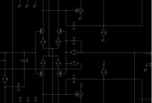
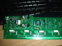
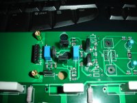
If i see well,two options.See the parts and the values for the normal (left) and normal (right) feedback options.
1)unmound two 120k change R15 to 27K// 2.2pf
2)mound two 1p2 //120k
Right?

Two options for check.
Try them both and see what you think. I'm interested to hear other's opinion on the nested feedback. Some testing numbers would be good for each option too!
It looks like it didn't take you long to master SMT work. Nice job! Those dual transistors can be a bit of a pain.
Ok i will mount two 1p2 to this channel and leave the other channel empty according to second option for a try.Try them both and see what you think. I'm interested to hear other's opinion on the nested feedback. Some testing numbers would be good for each option too!
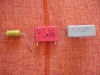
For d.c input blocker capacitor i have these, what is preferable to your opinion?
Unfortunately the 10uf don't feet well.
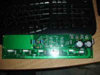
I want to go step by step so this IPS will be tested alone without OUT mounted.
Never i have done this in the past,but now using SMD this is necessary.😉
Attachments
Last edited:
Thanks,you,Valery,Evan ,give to me the opportunity to go for this.🙂It looks like it didn't take you long to master SMT work. Nice job! Those dual transistors can be a bit of a pain.
Last edited:
Ok i will mount two 1p2 to this channel and leave the other channel empty according to second option for a try.
For d.c input blocker capacitor i have these, what is preferable to your opinion?
Unfortunately the 10uf don't feet well.
I want to go step by step so this IPS will be tested alone without OUT mounted.
Never i have done this in the past,but now using SMD this is necessary.😉
Any one of those should work. The bass might roll off a little early with 2.2uF though.
I made up a jumper to plug into the bottom of my board with 100R resistors from PD+ and ND- to NFB for testing. It works well.
If i see well,two options.
1)unmound two 120k change R15 to 27K// 2.2pf
2)mound two 1p2 //120k
Right?
Right. Just don't forget - in the 1-st case R15 = 27K, in the 2-nd case R15 = 47K.
Any one of those should work. The bass might roll off a little early with 2.2uF though.
I made up a jumper to plug into the bottom of my board with 100R resistors from PD+ and ND- to NFB for testing. It works well.
Good tryk! I will do the same .Right. Just don't forget - in the 1-st case R15 = 27K, in the 2-nd case R15 = 47K.
Yes Valery i don't forget this(i hope so)

Right. Just don't forget - in the 1-st case R15 = 27K, in the 2-nd case R15 = 47K.
I'll put a note right on the schematics saying this. It will likely save some grief later.
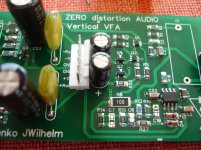
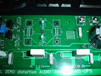
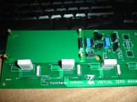
ZERO DISTORTION OUT
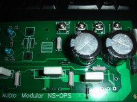
Some progress to power amplifier.
An easy to build power stage,clear, beautiful,i wish to play nice too!
This Monster will be alive soon😱
Some progress to power amplifier.
An easy to build power stage,clear, beautiful,i wish to play nice too!
This Monster will be alive soon😱
Attachments
Last edited:
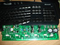
Some progress to power amplifier.
An easy to build power stage,clear, beautiful,i wish to play nice too!
This Monster will be alive soon😱
Jeff made an excellent modular layout.
Your build looks very clean 😎
Thanks Valery!Jeff made an excellent modular layout.
Your build looks very clean 😎
I hope this can play soon.🙂
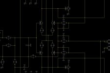
Looking around for the adjustment procedure (R31,R43).
My plan is to use one or two pairs of out transistors for this first test.😉
Last edited:
Looking around for the adjustment procedure (R31,R43).
Where i can find this adjustment procedure?
Where i can find this adjustment procedure?
Looking around for the adjustment procedure (R31,R43).
Where i can find this adjustment procedure?
If you go to Index at the 1-st page and click "NS-OPS", you end up here:
Building instructions
Just note - clockwise / counter-clockwise directions are mentioned there, based on the trimmers orientation at my 1-st prototype version.
Anyway, set the bias spreader to the maximum R position, the clamping spreader trimmer - close to the middle R.
First - you set the bias with no signal. Then - set the clamping with signal.
- Home
- Amplifiers
- Solid State
- Revisiting some "old" ideas from 1970's - IPS, OPS