Also, because jfets do not rely on the principal of forward biased semiconductor junctions, they are more resistant to RF than bjts in similar positions.
mlloyd1
mlloyd1
Also, because jfets do not rely on the principal of forward biased semiconductor junctions, they are more resistant to RF than bjts in similar positions.
mlloyd1
Yep! Good one.
that was really confusing...
😀
even with Modern Talking or Savage will be hard to test the sound of this extraordinary design
😉
how about Yuri Honing Trio "Walking On the Moon" to hear the viscera through the sax?
or Massive Attack "Angel"?
@ other people,
What tracks are you using to test the sound in new toys?
You have asked for directions. Here there are.
😀
even with Modern Talking or Savage will be hard to test the sound of this extraordinary design
😉
how about Yuri Honing Trio "Walking On the Moon" to hear the viscera through the sax?
or Massive Attack "Angel"?
@ other people,
What tracks are you using to test the sound in new toys?

what about this approach ?
http://www.diyaudio.com/forums/solid-state/148066-new-cherry-ndfl-amp.html
http://www.diyaudio.com/forums/solid-state/148066-new-cherry-ndfl-amp.html
what about this approach ?
http://www.diyaudio.com/forums/solid-state/148066-new-cherry-ndfl-amp.html
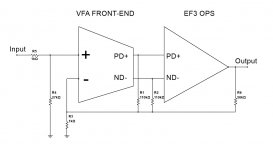
Definitely interesting approach. However, Cherry's goal was low frequency group delay compensation, while my goal is to reduce the loop gain of NFB loop around the output stage in order to keep overall distortion level low enough and have the amp's output impedance under control (not the lowest possible one).
For this purpose, I'm using 2 main frequency-independent feedback loops:
1) Local NFB loop, covering IPS and VAS only (OPS is out of this loop);
2) Global NFB loop, covering the whole amplifier, including the OPS.
Attachments

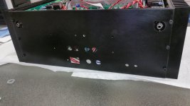
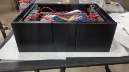
I've got a pair of Vertical VFAs with nested feedback running. They sound excellent! Now I need to get a chassis completed, and get them home for a proper audition.
Beautiful 😀
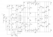
VZ-X - cool symmetric CFA front-end
Experimented with the diamond at the input in combination with controlled current sources in VAS stage.
Actually, started with single end driven VAS, but in the end came to fully symmetric topology - giving the lowest distortion and highest transparency.
Attached is the schematic with lateral FETs at the output. Good overall linearity, OLG is barely decreasing at 20KHz, so the distortion level is very low throughout the whole audio bandwidth.
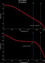
I also attach the modelled stability margins analysis - nice and clean loop gain and phase responses.
It's not live-tested yet.
Experimented with the diamond at the input in combination with controlled current sources in VAS stage.
Actually, started with single end driven VAS, but in the end came to fully symmetric topology - giving the lowest distortion and highest transparency.
Attached is the schematic with lateral FETs at the output. Good overall linearity, OLG is barely decreasing at 20KHz, so the distortion level is very low throughout the whole audio bandwidth.
I also attach the modelled stability margins analysis - nice and clean loop gain and phase responses.
It's not live-tested yet.
Attachments
That looks interesting Valery. Do you plan to build it?
Hi Carl, yes - it will take some time to design the layout, but I plan to build a prototype. I like the simplicity/performance ratio 😛
Hi Carl, yes - it will take some time to design the layout, but I plan to build a prototype. I like the simplicity/performance ratio 😛
Great! I enjoy and appreciate your work. I am especially fond of your TubSuMo. I listen to it every day in my office as I work. I look forward to building this.
Great! I enjoy and appreciate your work. I am especially fond of your TubSuMo. I listen to it every day in my office as I work. I look forward to building this.
Cool! Can you publish a few pictures of your implementation please? I also like TubSuMo a lot - just interesting to see the different builds, haven't seen yours as yet 😉
Cool! Can you publish a few pictures of your implementation please? I also like TubSuMo a lot - just interesting to see the different builds, haven't seen yours as yet 😉
Sure,
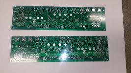
but nothing special in my build. The raw PCBs and power supply are resting undisturbed on a shelf. Ha, ha ...
I've got a chassis for it and similar sized project in the works. I will be sure to publish PICs then.
Last edited:
Hi Valery,
Could you have a look in your personal e-mail box? I sent you a PM. I became impressed with the performance in SIM of one of your TIS circuit and i liked to test other.
Please have a look!
TKS
Ronaldo
Could you have a look in your personal e-mail box? I sent you a PM. I became impressed with the performance in SIM of one of your TIS circuit and i liked to test other.
Please have a look!
TKS
Ronaldo
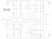
Virtual Zero X2
Continuing with "current drive" approaches, came up with this topology.
Excellent simulated performance, high open loop (as well as closed loop) linearity, great step response.
In combination with NS-OPS, the values of lead and shunt compensation capacitors have to be doubled. No Miller caps whatsoever 😎
This one will be prototyped 100% 😉
Special thanks to Hugh - some ideas came in as a result of recent conversation
Cheers,
Valery
Attachments

Valery,
This is an elegant topology, as good as I have ever seen in symmetrical design!
Thank you for your tick to our chat. Having built this with Jon, we both know it sounds very, very good, though your input stage is a more sophisticated, symmetrical version. I wonder how the sound presentation changes as you change the ratio of the injected VAS emitter current versus the VAS collector current?
The VAS is a twist of the Hitachi AN of 1972..... I wonder why they did not draw in the dots to make an emitter drive rather than a base drive?
Grounded base is a wonderful configuration, used in VHF and radar linear amplifiers.
Good to see Carl still building, hi Carl!
Hugh
Last edited:
Hi Valery,take care for a single sided pcb if it's possible😉Hi Carl, yes - it will take some time to design the layout, but I plan to build a prototype. I like the simplicity/performance ratio 😛
Last edited:
- Home
- Amplifiers
- Solid State
- Revisiting some "old" ideas from 1970's - IPS, OPS