This has been a great thread, but if values will not continue to be posted, then you will have to start a second thread in the Vendors Bazaar or another commercial area on our site for further discussion of any design without a full schematic. Its a standard diyA policy for all. Thanks.
Hi Salas, thank you for a friendly reminder 😉 Sure, the full schematic will be published as usual - preparing a more practical version, with rails filtering, etc. As well as the layout. PDFs (if I succeed to design a single-sided for etching) are normally published here, gerbers are available on request.
This particular one went here right from the simulator - simplified, cleaner view for demonstrating/discussing the principle.
Cheers,
Valery
Evolution is a spiral )))
OK... I think, this is very funny 😛
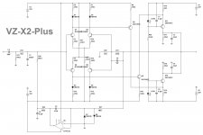
I continued playing with the topology and eventually a simple version with 2 x CCSs at VAS output showed the same performance as the initial "reference" topology - see attached.
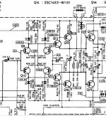
Then I touoght... I've seen something rather similar in some well-known commercial design. Looked up my archive - Bingo!
What happened? I have practically re-invented the front-end of Accuphase M60 😀
I consider it as a good "proof of concept" confirmation 😎
Well, there are still some improvements - I can use excellent low-voltage duals in input LTPs, easily scaling the output swing to any desired rails voltage, modern transistors are faster and higher beta, etc.
I have already tested this configuration earlier, but with no broken mirrors in LTP collectors. This one - with the mirrors - is better. Perfect phase response and better open loop linearity and bandwidth.
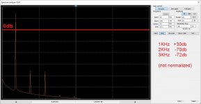
Simulated spectrum shows the dominance of the 2-nd and the 3-rd harmonics, and ... nothing above them.
OK. So far - so good. Coming closed to a "build-able" version.
Cheers,
Valery
OK... I think, this is very funny 😛
I continued playing with the topology and eventually a simple version with 2 x CCSs at VAS output showed the same performance as the initial "reference" topology - see attached.
Then I touoght... I've seen something rather similar in some well-known commercial design. Looked up my archive - Bingo!
What happened? I have practically re-invented the front-end of Accuphase M60 😀
I consider it as a good "proof of concept" confirmation 😎
Well, there are still some improvements - I can use excellent low-voltage duals in input LTPs, easily scaling the output swing to any desired rails voltage, modern transistors are faster and higher beta, etc.
I have already tested this configuration earlier, but with no broken mirrors in LTP collectors. This one - with the mirrors - is better. Perfect phase response and better open loop linearity and bandwidth.
Simulated spectrum shows the dominance of the 2-nd and the 3-rd harmonics, and ... nothing above them.
OK. So far - so good. Coming closed to a "build-able" version.
Cheers,
Valery
Attachments
Hi Valery,
One issue I have with this new version is the use of the two CCSs at the top and bottom of the VAS. This could be a potential place where the classic problem of symmetrical topologies shows it's head. The problem of the two halves fighting each other. Would be good to implement some sort of common mode control loop here? Have been thinking of how to do this but not worked it out yet...
Paul
Hi Valery,
One issue I have with this new version is the use of the two CCSs at the top and bottom of the VAS. This could be a potential place where the classic problem of symmetrical topologies shows it's head. The problem of the two halves fighting each other. Would be good to implement some sort of common mode control loop here? Have been thinking of how to do this but not worked it out yet...
Paul
Hi Paul,
The problem of the two halves fighting each other happens when LTP collectors are mirrored to each other. This is not the case here, so the VAS quiescent current will be constant and CMCL is not required.
Cheers,
Valery
Hi Paul,
The problem of the two halves fighting each other happens when LTP collectors are mirrored to each other. This is not the case here, so the VAS quiescent current will be constant and CMCL is not required.
Cheers,
Valery
This makes sense but should we be concerned about the effects of temperature? I'm thinking we need perfectly symmetrical current subtraction.
Or am I worrying about insignificant details?
Paul
This makes sense but should we be concerned about the effects of temperature? I'm thinking we need perfectly symmetrical current subtraction.
Or am I worrying about insignificant details?
Paul
This one is a working circuit, I have on my desk:
Vertical VFA front-end
Well, it worms-up during a few minutes - during this time the VAS idle current increases a bit. Then it settles and stays very stable. Well, different topology, but - also two halves, "looking at each other".
Cheers,
Valery
It''s starting to resemble a symmetrical V-hex input.
Yes - that's actually the one, with addition of two "broken current mirrors" at LTP collectors. And then - made symmetrical. VHex (as well as Ampliwire) is its "parent" 🙂
Yes - that's actually the one, with addition of two "broken current mirrors" at LTP collectors. And then - made symmetrical. VHex (as well as Ampliwire) is its "parent" 🙂
Valery, what do you call broken current mirrors?
Valery, what do you call broken current mirrors?
Hi Damir,
The ones where one of the diode-arranged transistors is replaced by an actual diode. It's less precise as a mirror, but when used with gain (2 resistors have different values), plus two of them are used symmetrically - lack of precision does not matter any more.
On the schematic in post #742 above those are two current mirrors:
1) D1, R6, Q5, R9
2) D3, R10, Q8, R19
D1 and D3 could be transistors with c-b shorted, then the mirrors would look more like mirrors 🙂
1) D1, R6, Q5, R9
2) D3, R10, Q8, R19
D1 and D3 could be transistors with c-b shorted, then the mirrors would look more like mirrors 🙂
I use similar CM in my CFA but as a CCS. Who was first to called it broken mirror?
Just saw it somewhere on the forum here 🙂 I find this name good enough for distinguishing this one from the "normal" mirror (with 2 transistors).
back to "four wheel drive"
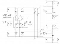
OK, I have returned to 4-points drive of the VAS output CCSs.
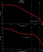
Excellent simulated performance - distortion, speed, phase response, transients handling, very clean clipping. Loop gain/phase curves are incredibly clean, the front-end is not "nervous" at all 😎
OLG is 70db throughout the audio bandwidth, CLG = 29db, LG = 41db.
Still not sure if I want to split R21 in 2 halves and ground the middle point or leave it floating. We'll see at the prototype 😉
OK, I have returned to 4-points drive of the VAS output CCSs.
Excellent simulated performance - distortion, speed, phase response, transients handling, very clean clipping. Loop gain/phase curves are incredibly clean, the front-end is not "nervous" at all 😎
OLG is 70db throughout the audio bandwidth, CLG = 29db, LG = 41db.
Still not sure if I want to split R21 in 2 halves and ground the middle point or leave it floating. We'll see at the prototype 😉
Attachments
R21 = you may put npn transistor with grounded base, thermal loss at top and bottom half tranies should be splitted 50/50. It should work nice.
VZ drive looks like a cherry on top of cake 😀
VZ drive looks like a cherry on top of cake 😀
R21 = you may put npn transistor with grounded base, thermal loss at top and bottom half tranies should be splitted 50/50. It should work nice.
VZ drive looks like a cherry on top of cake 😀
In this latest version I've got identical mirrors on both the top and the bottom sides, so one transistor with grounded base will not help any more. Possible solutions:
- one floating resistor as it is now (the simplest one 🙂);
- two resistors with grounded middle point;
- one floating CCS;
- two grounded CCSs.
I plan staying with the resistors for now.
To ground or not to ground - that is the question 😀
Better IMHO keep it simple (resistor) or just j-fet ccs in between.
At the LTP's very nice would be to putt dual NPN/PNP in smd.
What is roughly the bias at Q3 and Q5 etc ??
The whole ips can be fitted at very small board.
They may be usefull too:
-PZTA49/92
-BFN27/26
I found MPSA92/42 very good at VAS stage (i putt them in parallel if required), pzta have 1,2W so with a nice heat pads can be pushed a bit harder.
Last edited:
Better IMHO keep it simple (resistor) or just j-fet ccs in between.
At the LTP's very nice would be to putt dual NPN/PNP in smd.
What is roughly the bias at Q3 and Q5 etc ??
The whole ips can be fitted at very small board.
They may be usefull too:
-PZTA49/92
-BFN27/26
I found MPSA92/42 very good at VAS stage (i putt them in parallel if required), pzta have 1,2W so with a nice heat pads can be pushed a bit harder.
Exactly - I'm planning to use BC846BPN npn/pnp pairs in both LTPs and the output CCSs 😎
I'm finally starting up my Virtual Zero boards. I've got a bit of an issue with the front end.
R8,9,28,29 are all passing 6.75mA, but I'm only getting 8.2V at D1 &2. How much current should this input need?
R8,9,28,29 are all passing 6.75mA, but I'm only getting 8.2V at D1 &2. How much current should this input need?
Hi Jeff - my fault. Those 5.6K values are good for +/-70V...75V rails.
For around +/-50V rails those resistors have to be 2.7k.
In case you don't have those in hand, you can just add another 5.6k on top of each of those (in parallel). This will give us 2.8k, which is fine.
The price for simplicity of these 15v zener-based dividers - they have to be tuned-up for different rail voltages.
- Home
- Amplifiers
- Solid State
- Revisiting some "old" ideas from 1970's - IPS, OPS