Hi, Valery!Continuing with "current drive" approaches, came up with this topology.
Excellent simulated performance, high open loop (as well as closed loop) linearity, great step response.
In combination with NS-OPS, the values of lead and shunt compensation capacitors have to be doubled. No Miller caps whatsoever 😎
This one will be prototyped 100% 😉
Special thanks to Hugh - some ideas came in as a result of recent conversation
Cheers,
Valery

Maybe make it so?
Attachments
...Good to see Carl still building, hi Carl!Hugh
Yup,
It's great to see you here as well Hugh! Valery is doing great work and is a generous fellow to work with.
I invite everyone reading this thread to visit his website. That too is especially well done. It is here ... vzaudio
Carl, thank you for the warm feedback 🙂
I'm going to take a break for designing new circuits and focus on finalizing some stuff I did earlier. Both VZ-X and VZ-X2 layouts are under development now - will let you know when ready 😉
I'm going to take a break for designing new circuits and focus on finalizing some stuff I did earlier. Both VZ-X and VZ-X2 layouts are under development now - will let you know when ready 😉
Carl, thank you for the warm feedback 🙂
I'm going to take a break for designing new circuits and focus on finalizing some stuff I did earlier. Both VZ-X and VZ-X2 layouts are under development now - will let you know when ready 😉
Your giving us some time to catch up!😎
Hi, Valery!
Maybe make it so?
Hi! Looks good 😎 2-nd beta-enhanced LTP allows a lot of OLG, although I'm trying to keep my global loop gain not too high. I also like the double-driver stage, although I would use a separate base stopper for each output device.
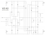
Virtual Zero X2 - reference topology
A final touch - 2 diodes added.
The one at the top shoulder of balanced VAS makes the mirror even more precise, the one at the bottom makes clipping exactly symmetric.
No rail sticking or other artifacts by design - none of the transistors go into deep saturation 😎
BC846BDW1/BC856BDW1 duals will fit perfectly for LTPs.
Working on the layout
Attachments
Need plus two diode in the lower shoulder and one extra to throw away.A final touch - 2 diodes added.
Anyway, look at the diagram carefully: it is still possible to optimize with increasing gain.
Need plus two diode in the lower shoulder and one extra to throw away.
Anyway, look at the diagram carefully: it is still possible to optimize with increasing gain.
Hi,
Could be wrong but I see the potential to add some ips current mirrors to this?
Also, could the diodes in the top half of the VAS be replaced by diode connected transistors? Thereby making more "classical" current mirrors.
Valery - Your current driven VAS designs are extremely interesting. Can't wait to get my PC rebuilt. 🙂
Paul
Last edited:
Need plus two diode in the lower shoulder and one extra to throw away.
Anyway, look at the diagram carefully: it is still possible to optimize with increasing gain.
I deliberately keep the open loop gain limited. It's only 64db at the moment.
Hi,
Could be wrong but I see the potential to add some ips current mirrors to this?
Also, could the diodes in the top half of the VAS be replaced by diode connected transistors? Thereby making more "classical" current mirrors.
Valery - Your current driven VAS designs are extremely interesting. Can't wait to get my PC rebuilt. 🙂
Paul
Hi Paul,
I'm using 5 "broken" current mirrors here - 4 of them are in IPS (LTP) collectors and one of them (high-precision) is at the top of VAS.
The diodes can be replaced by diode-connected transistors for sure, I'm just saving some transistors - after all, there will be a commercial version of this amp 😉
However, in this particular design, replacing the diodes will not really improve anything - IPS current mirrors are asymmetric (mirrors with gain), so we don't need precision there. The one in VAS works well because it's an "improved" Wilson one - very good anyway 🙂
Need plus two diode in the lower shoulder and one extra to throw away.
Anyway, look at the diagram carefully: it is still possible to optimize with increasing gain.
Hi, the diodes in the emitters - not really good as I need to increase my voltage reference in this case - more parts again. The diode at the bottom collector does not hurt at all - just limiting the bottom half of the swing.
I deliberately keep the open loop gain limited. It's only 64db at the moment.
Infinity is not a limit. 🙂
Hi!The transistors at the output of the VAS is possible to rock on the base circuit and emitter circuit. In addition, the two halves of the VAS should be symmetrical.Hi,
Could be wrong but I see the potential to add some ips current mirrors to this?
Also, could the diodes in the top half of the VAS be replaced by diode connected transistors? Thereby making more "classical" current mirrors.
Valery - Your current driven VAS designs are extremely interesting. Can't wait to get my PC rebuilt. 🙂
Paul
Hi!The transistors at the output of the VAS is possible to rock on the base circuit and emitter circuit. In addition, the two halves of the VAS should be symmetrical.
I think I understand what you mean, but the "beauty" of this balanced VAS output stage is in its "asymmetry" - the bottom side sets the quiescent current, based on the voltage reference (TL431), the top one - is the current mirror, ensuring the top half operates at exactly the same quiescent current.
And then I drive this balanced "ring" at 4 points, subtracting the currents symmetrically. No base voltage drive - this is the key! Only currents subtraction. That's what ensures very high open loop linearity in the whole front-end.
Overall structure - V-to-I conversion in the LTP, then linear current increase, and then I-to-V conversion in the balanced VAS output stage (4-points current drive).
If we needed a beauty... 🙂 But we need linearity."beauty" of this balanced VAS output stage is in its "asymmetry"
If we needed a beauty... 🙂 But we need linearity.
Exactly! But not by the means of high gain, "killed" by negative feedback. That's what the circuit is all about. Native linearity. That's where the good sound is 😎
Valery,
Thank you for your reply.
I understand about it becoming a commercial design. That'll be why the component values are missing. 😉 there are also some finer details that I have missed... Mirrors with gain.
Think we are similar in our design objectives. I too use low loop gain these days. The difference being that I currently go all out for speed and use high ulgfs. Degeneration has also made a come back in a big way.
Do have one idea for a variant but will have to get some functional computing power first. Not as advanced as you or t117. Have to change confirm with simulation first.
Appreciate you sharing these ideas!
Paul
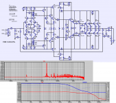
Victor, especially for you.
If I remove NFB and decrease degeneration, I can easily reach OLG = 92db (much more than I need, but just for test).
Bandwidth is still slightly wider than 20KHz, by the way.
Simulated THD in this case - open loop - is slightly less than 0.06%.
Now, let's close the loop, setting CLG = 29db (standard).
That gives us LG = 63db = 1413 times.
Divide 0.06% by 1413 times - you will get theoretical THD < 5 ppb (parts per billion).
5E-07%. Stability margins are not as good as the ones in original setup, but still acceptable. For sure, live build will add some issues, but nobody needs the level of distortion to be that low.
My practical build will have THD at the level of 5-10 ppm throughout the audio bandwidth (more than enough). What is much more important - having only 35db of the loop gain gives a lot of advantages. Unconditional stability, high enough slew rate, low intermodulation, soft clipping, excellent step response.
Current drive gives lots of freedom. You can move "The Compromise" rather far in any direction you like. If you know what I mean 😉 Huge potential for experiments and further developments 😎
Valery,
Thank you for your reply.
I understand about it becoming a commercial design. That'll be why the component values are missing. 😉 there are also some finer details that I have missed... Mirrors with gain.
Think we are similar in our design objectives. I too use low loop gain these days. The difference being that I currently go all out for speed and use high ulgfs. Degeneration has also made a come back in a big way.
Do have one idea for a variant but will have to get some functional computing power first. Not as advanced as you or t117. Have to change confirm with simulation first.
Appreciate you sharing these ideas!
Paul
Hi Paul,
Right, I also came to understanding that I like relatively low global loop gain.
I made a number of very fast CFA designs - great natural sound in mids-highs, however those designs gave me a strange feeling of "too much control" over the speaker in the bass region. At that time I have designed a non-switching OPS - low distortion open loop, giving me a lot of freedom for lower loop gains experiments. "Vertical VFA" with 2 feedback loops, allowing lower loop gain for OPS (less control over the load), sounds delicious, at least with my speakers.
Current drive is a new platform, giving even more freedom 🙂 Combination of natural linearity, clean phase response and overall speed - exactly what I'm looking for.
It would be cool to see your idea 😉
 This has been a great thread, but if values will not continue to be posted, then you will have to start a second thread in the Vendors Bazaar or another commercial area on our site for further discussion of any design without a full schematic. Its a standard diyA policy for all. Thanks.
Last edited by a moderator:
- Home
- Amplifiers
- Solid State
- Revisiting some "old" ideas from 1970's - IPS, OPS