Valery
I was thinking about this from the beginning...
btw what is output impedance/DF of your NS-OPS?
Hi Pawel,
I did not measure on the live prototype yet, but simulation shows the following:
- OPS within GNFB: Zo = 0.4 mOhm (milli-ohm);
- OPS out of GNFB: Zo = 0.1 Ohm.
250 times difference = 48db, that's exactly the feedback loop gain 🙂
Laws of physics are working as usual 😛
Maybe a moderate of global fb would be best, say 25-30dB?
Hi Hugh,
You're revealing my "secret" 😀
Yes - nested feedback. In fact the best result is achieved when splitting these 48db loop gain between the global loop and the loop around the front-end.
I'm still experimenting with regards to the best proportion, although in principal it seems to be a very good approach. Our "production" PCB for Vertical + NS-OPS (designed by Jeff) already incorporates this feature.
Cheers,
Valery
Another "old" possibility as an alternative FB method:
The ALTMANN SPLIF Amplifier Topology
Or you can adjust it to the "middle" with a (0 - 1R) resistor between the protected pair and the load driver pair(s).
Altman's approach does not make too much sense to me as the protected pair works with no load - so, it's almost the same as just connecting the feedback to VAS output. Connecting the protected pair to the loaded one with resistor - yes, that's interesting. Some room for experiments 😉
If I would have an A/B testing system, as good as Terry has - I would probably be able to have a clearer comparison. Anyway - worth trying!
Cheers,
Valery
I have an A/B test system idea brewing. A 4 channel preamp and four SS relays would do nicely here. Arduino controlled switching and volume matching would be slick.
vertical CFA+Slewmaster out
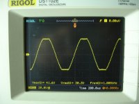
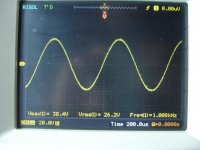
A first test done putting 47pf in position of c18,19 .This test wasn't successful. Then the compensation increased to 68pf. That's it!The problem solved.
A full test later this afternoon.
Thimios
A first test done putting 47pf in position of c18,19 .This test wasn't successful. Then the compensation increased to 68pf. That's it!The problem solved.
A full test later this afternoon.
Thimios
A first test done putting 47pf in position of c18,19 .This test wasn't successful. Then the compensation increased to 68pf. That's it!The problem solved.
A full test later this afternoon.
Thimios
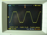
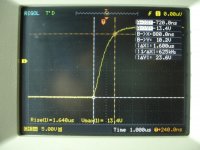
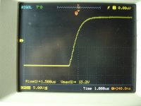
OK - VAS does not like that additional pole from the OPS 🙂
BTW, this cap value increase will practically not slow down the overall front-end's step response. Looking forward to seeing your test results 😎
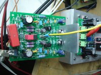
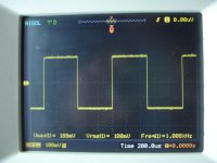
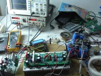
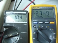
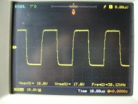
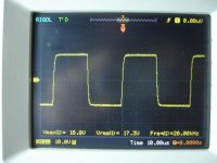
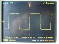
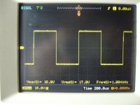
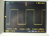
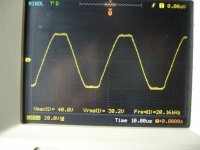
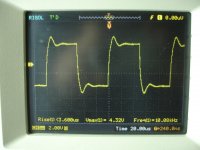
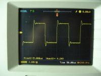
Testing vertical CFA+Slewmaster
Power supply +/-50v
54000uf/rail
Idle current 54mA/Pair
Offset 0mV
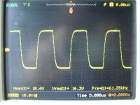
1V RMS INP 27 V RMS OUT/6R=120W RMS.Before a visible clip.
Power supply +/-50v
54000uf/rail
Idle current 54mA/Pair
Offset 0mV
1V RMS INP 27 V RMS OUT/6R=120W RMS.Before a visible clip.
Attachments
-
 DSC09679.JPG585.2 KB · Views: 722
 -
 DSC09689.JPG515.5 KB · Views: 192
 -
 DSC09688.JPG540.6 KB · Views: 179
 -
 DSC09687.JPG548.8 KB · Views: 207
 -
 DSC09686.JPG519.5 KB · Views: 194
 -
 DSC09685.JPG548.2 KB · Views: 250
 -
 DSC09684.JPG562.6 KB · Views: 655
 -
 DSC09683.JPG559 KB · Views: 656
 -
 DSC09682.JPG607 KB · Views: 649
 -
 DSC09681.JPG563.8 KB · Views: 706
the rest
Attachments
-
 DSC09701.JPG577 KB · Views: 191
 -
 DSC09699.JPG511.8 KB · Views: 187
 -
 DSC09698.JPG611.8 KB · Views: 185
 -
 DSC09697.JPG535.7 KB · Views: 179
 -
 DSC09696.JPG533.6 KB · Views: 172
 -
 DSC09695.JPG582.6 KB · Views: 156
 -
 DSC09694.JPG536.9 KB · Views: 138
 -
 DSC09693.JPG597.1 KB · Views: 150
 -
 DSC09691.JPG530.4 KB · Views: 159
 -
 DSC09690.JPG597.2 KB · Views: 181
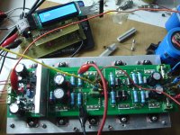
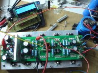
Not yet....just for a little.Looks good, huh? 😉
Did you listen to it?
I have some other test
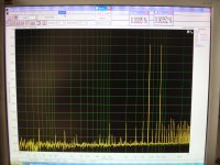
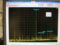
Doing this test i see that,connecting speaker GND on power amplifier board is a bad practice.
Star GND is better.Even better a second clean GND position.
Attachments


Last edited:
Too late for edit.
See this photo with speaker GND connected on power amplifier pcb,look at 50Hz and all other harmonic up to 1KHz
I think there is some loop in your grounding scheme in this case - mine is dead silent with the input connected to the pre-amp.
Am I right - at the previous measurements the speaker ground is connected to PSU ground?
Yes in all the previous measurements the speaker gnd is connected to psu gnd and the devider gnd on psu gnd.Hot cable of devider is connected to speaher out on pcb, behide R.LI think there is some loop in your grounding scheme in this case - mine is dead silent with the input connected to the pre-amp.
Am I right - at the previous measurements the speaker ground is connected to PSU ground?
How you avoid the gnd loop?
Last edited:
In the meanwhile i made some minutely tests on my vertical ns-ops. I am very curious if thimios confirms them.
Pros:
The most distortion-less and clear CC Catch playing that i ever heard
Cons:
Heights-a little too sterile for my taste. My classA amp sounds sweeter.
Lows-too flat, week and heartless.I am exaggerating!!! Hint: i only use 20000uF per rail
Conclusion: if you like CC Catch this is the amp
Pros:
The most distortion-less and clear CC Catch playing that i ever heard
Cons:
Heights-a little too sterile for my taste. My classA amp sounds sweeter.
Lows-too flat, week and heartless.I am exaggerating!!! Hint: i only use 20000uF per rail
Conclusion: if you like CC Catch this is the amp
In the meanwhile i made some minutely tests on my vertical ns-ops. I am very curious if thimios confirms them.
Pros:
The most distortion-less and clear CC Catch playing that i ever heard
Cons:
Heights-a little too sterile for my taste. My classA amp sounds sweeter.
Lows-too flat, week and heartless.I am exaggerating!!! Hint: i only use 20000uF per rail
Conclusion: if you like CC Catch this is the amp
There is a special option for this kind of situation now - Vertical VFA with nested feedback - it's warmer and sweeter (NS-OPS is the same). Listening to it right now - jazz trio sounds brilliant 😎
please alight me
is cc catch any idiom?
what does it mean?
only the band name?
The band, yes... I think 🙄
please alight me
is cc catch any idiom?
what does it mean?
only the band name?
CC Catch = Caroline Catharina Müller. A famous german/dutch singerin of 80's. Am I right?
- Home
- Amplifiers
- Solid State
- Revisiting some "old" ideas from 1970's - IPS, OPS