Could you measure a few points of the frequency response of your favourite filter? It's particularly the transition band that matters.
I assume it must be some sort of Gaussian tapered sinc rather than a "real" Gaussian filter, as its roll-off would otherwise be much too slow. The trick is to find out how wide the Gaussian taper must be.
HQPlayer poly-sinc-gauss:
Marcel 1p4:

Will give DSD512 from HQ Player a try in maybe a few days. Need the dac in its normal DSD256 state for a few days first.
There is a new PCB version for pcm2dsd, it has a connector with FPGA pins, as needed by @MarcelvdG firmware 1p2
https://www.diyaudio.com/community/threads/simple-dsd-modulator-for-dsc2.370177/post-7841496
https://www.diyaudio.com/community/threads/simple-dsd-modulator-for-dsc2.370177/post-7841496
@Markw4
You favored using Metal Foil resistors at the shift registers output.
I was just looking at a Bruce Hofer presentation from AP where amongst others, resistor properties were discussed.
Apart from their excellent Tc and Vc properties above 1Khz, are you aware of their large deviating properties between 10-200Hz ?
Hans
Attachments
Hi Hans,
Hofer has said somewhat different things at different times. In one article he said:
.... My recent experiments (which are also corroborated by another individual) show that some metal foil resistors with exceptionally low TCR behave as if | Z(ω)| >> θR, thus contributing higher modulation distortion than a thin film resistor with a larger TCR under identical conditions.
Please see pages 3, 4 of: https://convexoptimization.com/TOOLS/HoferUltraLowTHD+NPart2.pdf
Without knowing which metal foil resistors he was talking about, whether they were T/H or SMD, etc., makes it kind of hard to know under what conditions such thermal modulation might be seen.
In the two cases where metal foil resistors were tried here, they resulted in come improved clarity. In the case at that time with the RTZ dac the improved clarity was deemed to be only very slight and not worth the added cost.
Mark
Hi MarK,
As always, you are well documented.
However in the link you provided, I also read:
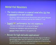
Reducing Temperature Coefficient Nonlinearity
Avoid the common 25-ppm/C characteristic in critical circuit locations. Instead, opt for premium parts that deliver 10-ppm/C or even 5-ppm/C characteristics.
Avoid metal foil resistors. While they have very low temperature coefficients (less than 1 ppm/V), they exhibit poor AC performance. This information isn’t found in the datasheets, which typically only show DC values.
However, technical specifications and listening experience are two different things,
So, AP purely concentrating on the highest possible technical performance, is looking at it from a different angle as you do as a listener.
I have no experience with metal foils, but I was nevertheless rather surprised by this information.
Hans
As always, you are well documented.
However in the link you provided, I also read:
Reducing Temperature Coefficient Nonlinearity
Avoid the common 25-ppm/C characteristic in critical circuit locations. Instead, opt for premium parts that deliver 10-ppm/C or even 5-ppm/C characteristics.
Avoid metal foil resistors. While they have very low temperature coefficients (less than 1 ppm/V), they exhibit poor AC performance. This information isn’t found in the datasheets, which typically only show DC values.
However, technical specifications and listening experience are two different things,
So, AP purely concentrating on the highest possible technical performance, is looking at it from a different angle as you do as a listener.
I have no experience with metal foils, but I was nevertheless rather surprised by this information.
Hans
We though tantalum nitride sounded unacceptably distorted for the DSD dac. In Italy they liked them for the R2R dac. The listening here and the listening there was done on two very different systems. Here we use electrostatic speakers. There, IIUC, they were using horn speakers.
Also, the above reported experiences were before I found the various problems with ferrites and nonlinear capacitors. After some modifications to fix those problems on the Andrea Mori DSD dac, it started sounding a lot better. So I think the TN resistors might have been even more objectional at that point. Information on the findings was sent to Andrea.
Also, the above reported experiences were before I found the various problems with ferrites and nonlinear capacitors. After some modifications to fix those problems on the Andrea Mori DSD dac, it started sounding a lot better. So I think the TN resistors might have been even more objectional at that point. Information on the findings was sent to Andrea.
It seems to me more like your problem was with the ferrites because I also had oscillations on some other projects using ferrite coils in filters, removing them completely fixes isues. I still have tantalum nitride in one of the dsc2 dac projects in my main system, sound ok. Might depend on manufacturer? I'm used PTN1206E from Vishay. In theory it should work very good with very small drift caused by teperature change in comparation to other types. Anyway thanks, just wanted to hear opinion.
The ferrites were the worst of the two problems, but going to more linear caps was helpful too. I tried one thing at a time so the effect of each change could be noted.
Whats opinion about tantalum nitride thin film resistors?
That you should check the manufacturer's conflict mineral statement when you want to buy something made of tantalum, tungsten, tin or gold, although I must admit I often forget to do so. Otherwise I have no opinion.
What is opinion about DualMEMS and TurboCompensation Temperature Sensing Technology for our audio dac's? I am shocked! Even I am surprised with SiT9387 which have 0.23 ps RMS (typ) phase jitter (random, 12 kHz to 20 MHz) , all that seen today for the first time and it exist from 2018 year!
Attachments
^They don't show phase noise plots, however clocks rated for low jitter from 12kHz to 20MHz offset are arguably not necessarily optimal for audio. OTOH, ultra-low close-in phase crystal noise clocks often recommended for audio may be rated for exceptional performance from 0.1Hz to 1Mhz offset, or something more like that.
Ofcorse! That was just for SiT9387 but did you saw video link from pdf for our dual mem with turbo sensing compensation? On the video is an comparation with 50ppb tcxo, and our dual mem is 100ppb, brutal! Video is from 8 years ago, I can't believe only 2.7k views. I didn't know there was such a thing until today : ) And searched a bit to where it can be bought but found only link for contact, does it exist on ic markets for buy?
Last edited:
Okay. But what crystal TXCO? What are its other specs? What do abrupt temperature variations have to do with a dac?On the video is an comparation with 50ppb tcxo, and our dual mem is 100ppb...
I'm just asking because you're here in one place, has anyone tried this tcxo, that's all! Nevermind. I managed to find them, but they are out of stock 🙂
https://www.digikey.com/en/product-highlight/s/sitime/sit5156-series-super-tcxo
https://www.digikey.com/en/product-highlight/s/sitime/sit5156-series-super-tcxo
Thats interesting. So theoretically Wirewound would be the best? That would induce parasitic inductance or capacitance depending on the winding scheme.Hi MarK,
As always, you are well documented.
However in the link you provided, I also read:
Reducing Temperature Coefficient Nonlinearity
Avoid the common 25-ppm/C characteristic in critical circuit locations. Instead, opt for premium parts that deliver 10-ppm/C or even 5-ppm/C characteristics.
Avoid metal foil resistors. While they have very low temperature coefficients (less than 1 ppm/V), they exhibit poor AC performance. This information isn’t found in the datasheets, which typically only show DC values.
However, technical specifications and listening experience are two different things,
So, AP purely concentrating on the highest possible technical performance, is looking at it from a different angle as you do as a listener.
I have no experience with metal foils, but I was nevertheless rather surprised by this information.
Hans
Mute on Pin-137 are Input or Ouput.Attemping to put all the information in one post, so I can easily link to it from post #1:
Attached is the .bit file and source code that puts two of my PWM8 modulators and a two-channel FIR filter in an XC6SLX9-2TQG144C (or XC6SLX9-2TQG144I, if you want it to keep working when it is freezing cold). I have gone to speed grade 2, because faster was apparently not needed and speed grade 2 is also what is used in PJotr25's and olo111's simple DSD modulator for DSC2 (a.k.a. PCM2DSD). I also managed to squeeze in an extra filter for filtering and remodulating DSD input signals. The input violates the I2S hold time specification by 0.8 ns, but that is not likely to cause any problems.
PJotr25 and Markw4 have tried it in real life. With a lot of help from PJotr25, I found and fixed a bug in the FIFO controlling part.
The idea behind the modulator is explained in https://linearaudio.net/sites/linearaudio.net/files/03 Didden LA V13 mvdg.pdf pages 32...34 (pdf pages 10...12). It's a quasi-multibit modulator of which the quantizer is dithered according to dither theory, which eliminates the frequency-modulated idle tones around half the sample rate that you have with straightforward single-bit modulators and also their intermodulation products that can otherwise end up in the audio band. You pay for that with less effective noise shaping, hence it has to work at a high bit rate. The FIR interpolation filter output is also rounded with dither (and only rounded down to 35 bit word length).
For PCM, the interpolation chain consists of an 8 times interpolating FIR filter that can be set to steep or apodizing, a zero-order hold and the fifth-order low-pass signal transfer function of the sigma-delta modulator. For remodulated DSD, a 15-tap FIR filter with triangular impulse response, zero-order hold and the fifth-order low-pass signal transfer function of the sigma-delta modulator.
It is supposed to be completely compatible with PCM2DSD, but the output is at a DSD512 rate, so reclocking with the 22.5792 MHz or 24.576 MHz is not going to work, not without double edge clocking anyway. Using the master clock as the bit clock for the DAC should work, though.
There are a couple of conditions:
-It is designed to support PCM sample rates from 8 kHz up to and including 192 kHz and DSD from DSD64 up to and including DSD512 (both 44.1 kHz- and 48 kHz-based). That is, there is no support for 384 kHz PCM.
-The input accepts word lengths up to 32 bit.
-When playing PCM, the master clock must be an exact multiple of 64 times the sample rate, as it usually always is
-The master clock must be in the range from 19 MHz to 25 MHz, the normal values are 22.5792 MHz and 24.576 MHz.
Several pins that are open on the PCM2DSD board can be made high or low to activate extra functions. They have internal pull-ups and pull-downs, so when you leave them open, everything works normally.
"mute" on pin 137: internally pulled low, high level mutes the sigma-delta modulator
"scale[1]" on pin 117: internally pulled low, high level makes sigma-delta input 12 dB more sensitive, can be useful as a debug function to check the effect of overload
"scale[0]" on pin 119: internally pulled high, low level attenuates the signal by 6 dB so you have 6 dB extra headroom for intersample overs
"notSevenofNine" on pin 9: internally pulled high, low level allows only 7 out of the 9 quantization levels
"rot" on pin 7: internally pulled high, low level stops the random rotation function
Making pins 7 and 9 low could be useful for a NRZ FIRDAC of a multiple of eight taps long, like the DSC2.5.2. You then get a normal noise-shaped PWM signal that always has at least one one and at least one zero in each eight clock cycles. The average density of low-to-high and high-to-low transitions then becomes signal-independent. The disadvantage is that you get tones around 1/8 of the master clock rate and its multiples.
"notapodizing" on pin 141: internally pulled high, making it low changes the interpolation filter into an apodizing filter (smoother roll-off).
"dsdviasd" on pin 139: internally pulled high. When high, a DSD input signal gets filtered and remodulated, when low, a DSD input signal is only resynchronized to the master clock and forwarded to the output (transparent mode).
There is also one extra output:
"iclip" at pin 115: output that goes high for a bit less than a second after an integrator clips. It indicates that an intersample overshoot is larger than the modulator can handle, so you could make scale[0] low to solve that.
I was thinking that it automatically sets the H/L state based on the I2S/DSD data being sent - i.e. it is an output. This makes the PCM2DSD not need a Mute signal pin at the input!?
Correct me if I am wrong. Thanks.
- Home
- Source & Line
- Digital Line Level
- Return-to-zero shift register FIRDAC