This is not about comparing modulators. As measurements have shown this RTZ dac has pronounced distortions at low level with certain modulators. Marcel gave an explanation why quasi-multibit modulators work well but e.g. HQPlayer modulators are IP protected. I presented sox-dsd measurement as the source code for that modulator is freely available so it can be used as basis for further analysis if needed.Do you think it makes a lot of sense to look at HD at a particular signal level only when comparing modulators?
https://github.com/mansr/sox/blob/master/src/sdm.c
Okay. Is this getting us closer to understanding the cause? I mean if other RTZ dacs don't exhibit the same symptom, they why not drive this dac with crystal clocked RTZ to isolate the drive signal generation from the dac array behavior? Or what about more power supply isolation of different circuitry? Might that type of thing narrow the search for the particular circuitry responsible for producing the distortion? If such sleuthing helps tease out the distortion mechanism, then don't we only need one pathological modulator to do testing of the dac itself? Just thinking out loud here, not trying to be critical.
Marcel,
Do you think it makes a lot of sense to look at HD at a particular signal level only when comparing modulators? What about the old stepped DC offset versus noise metric?
Mark, thanks for bringing that up. I don't think anyone has been looking for harmonic distortion recently, but rather for a weird non-harmonic distortion caused by intermodulation between the frequency components of the FM-like spectrum of the modulator.
It should also be possible to find such intermodulation using a sigma-delta modulator converting a suitable DC offset. That should be easier to simulate and to measure. At least you don't have to distinguish frequency components at very small frequency offsets or to suppress a desired signal at a nonzero frequency.
I'll see if I can program a particularly poor sigma-delta modulator and have it convert an offset such that the second-order intermodulation product ends up at a highish audio frequency.
IOW, I believe its probably a Focusing Illusion bias.
Nasiruddin looking for his house keys under a lamp.
The observed spurs are merely a visible symptom of a problem that is not per se classic nonlinearity.
As we all know, simple systems commonly have highly complex problems.
The system of modulator, DAC, analogue stage etc. does I believe qualify as mildly unsimple and thus problems tend to mildly complex.
And we need to distinguish between observing a symptom of a mechanism that causes observable signal fidelity impairment and / or audible fidelity impairment, diagnosing the root cause and applying fixes. Six Sigma Evangelist here, in a previous life.
I would again suggest noise loading* as method and the use of a -6dB to -90dB noise loading signal with stepped DC offset sounds like a great way to get a better view at the symptoms.
I would probably also suggest using a multichannel 300 MHz 'scope with an active differential probe (I designed, made and validated one for more at one point while designing an analogue domain USB isolator, found it very useful afterwards) and poking it around the PCB at all clock and signal nodes, both transient and infinite persistence.
And I'd probably do an set of tests on just the digital domain side of the modulator(s).
Just saying. We need to remember that digital is only digital as long as it strictly in the digital domain (computer/sim only), in the real world all digital is actually analogue.
Thor
* Noise loading is basically "multitone" with tones replaced by band limited white noise bands with bands of silence between noise bands. In the analogue days we used tuned complementary LC comb filter and comparison to loopback.
No FFT, No spectrum. Just total residual with and without DUT. Each test needed manual tuning of adjustable chokes on both sides for absolute minimum on loopback, extremely fiddley.

Okay. Is this getting us closer to understanding the cause? I mean if other RTZ dacs don't exhibit the same symptom,
Do they?
The amount of "crazy" low level stuff I observed with DS but could not hear was a lot. At the same time, systems measuring very good and without problems showed on listening pronounces VERY LOW LEVEL birdies audible only at songs fading in/out at EXTREMELY low levels, but with the right part of an actual DSD file and enough gain (arguably enough to kill your hearing if you were suddenly got a 0dBDSD signal) extremely audible.
I never quite was able to answer if these birdies (idle tones, limit cycles of modulators whatever) disappeared suddenly with enough music level or simply became masked but persisted. Their non-steady state nature meant they were basically impossible to capture on an AP2 FFT.
What I do know, in blind preference tests, the systems without low level birdies, despite relative poor objective performance, scored more highly than the systems with better technical performance but low level birdies.
Incidentally, to my best knowledge all systems were RTZ with 75% Duty Cycle. We chased our collective tails over this for many month. Eventually we decided to cut losses and went with "no birdies, measures sh!t, sounds good" strictly empirically.
Again, just saying.
Thor
Correct. I believe I’m right in saying that neither Tidal nor Qobuz have DSD files.I think the question was if River was able to convert wav/flac to DSD on the fly...
Do Tidal send DSD... don't think so... hence the question...
//
Thx Marcel for pointing at the LTSpice setting.
I could, by making changes, go to a 0.2 nsec timestep where now all spikes from the Firdacs are vanished and nevertheless the needed hard disk space has been largely reduced.
I am making good progress with 6 different reconstruction filters, both active and passive.
When I’m ready I will show them all with their resp. frequency responses.
@Bohrok, could it be possible to provide me with a DSD128 .dsf file having 1Khz@-60dB that would produce on your system those anomalies ?
That would be great to enable finalising my sims
The one I have is made with a quasi-multibit converter from a .wav file, that’s why.
Hans
I would not call them anomalies. Different modulators cause varying degree of harmonics with other dacs as well. Harmonics with RTZ are just higher in some cases.
Whatever we can call them, FM products if you prefer.
But what about my question, would it be possible to provide a 1Khz@-60dB .dsf file, where on your system the file's response is known with all the non harmonic spectral lines.
That will enable comparing the right way, apples to apples.
Hans
But what about my question, would it be possible to provide a 1Khz@-60dB .dsf file, where on your system the file's response is known with all the non harmonic spectral lines.
That will enable comparing the right way, apples to apples.
Hans
I'll see if I can program a particularly poor sigma-delta modulator and have it convert an offset such that the second-order intermodulation product ends up at a highish audio frequency.
Plain old fifth-order single-bit sigma-delta modulator running at a DSD64 rate, with no dither and almost no chaos, notches at 10 kHz and 20 kHz, offset applied that should shift the main idle tone by 5 kHz and thereby cause a 10 kHz intermodulation product.
Spectrum with a 1 kHz, -60 dB DSD signal, Hann window, frequency axis in DFT bins of 100 Hz each, vertical axis in dB DSD:
Red trace: ideal case
Green trace: bit of second-order intermodulation distortion introduced by making the bit weight 0.1 % too high or 0.1 % too low, depending on the value of the previous bit.
Zoom of the 1.4 MHz to 1.42 MHz area, ideal case, spectrum above 1.4112 MHz is the mirror image of the part that is shown:
Spectrum without the 1 kHz signal, Hann window, frequency axis in DFT bins of 100 Hz each, vertical axis in dB DSD:
Red trace: ideal case
Green trace: bit of second-order intermodulation distortion introduced by making the bit weight 0.1 % too high or 0.1 % too low, depending on the value of the previous bit.
For some reason the 10 kHz peak is closer to 9.4 kHz. The second-order intermodulation distortion increases its level by about 70 dB. Source code attached (with the extension changed from .pp to .txt), next step: putting it into the program with the .dsf writing routine.
Attachments
See the attachment. If I didn't mess up, the DSD64 .dsf file has 10 seconds of only offset left and of a -60 dB DSD, 1 kHz sine wave and offset right, offset chosen to produce intermodulation at 10 kHz (or 9.4 kHz?). The Pascal program that generated the .dsf is also in the zip file.
Attachments
I'm not sure about your expectations but here are results from both RTZ (stock) and AK4493.Plain old fifth-order single-bit sigma-delta modulator running at a DSD64 rate, with no dither and almost no chaos, notches at 10 kHz and 20 kHz, offset applied that should shift the main idle tone by 5 kHz and thereby cause a 10 kHz intermodulation product.
Attachments
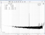
Interesting that there is only some 10 dB of difference around 10 kHz.
Was the AK4493 in volume bypass mode, DSDD = 1? If so, does it much improve with DSDD = 0? I would expect near perfect behaviour when DSDD = 0, especially on the left channel, unless something has gone wrong on my side.
How does the spectrum look for the left channels of both DACs?
Was the AK4493 in volume bypass mode, DSDD = 1? If so, does it much improve with DSDD = 0? I would expect near perfect behaviour when DSDD = 0, especially on the left channel, unless something has gone wrong on my side.
How does the spectrum look for the left channels of both DACs?
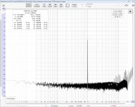
Silly me, I looked at the shapes rather than the shapes and scales. The worst peak around 10 kHz for the AK4493 is about -140 dB, and the peaks I simulate for the ideal case have about the same level. The main difference is that they are sticking out more above the noise in the measurements due to the smaller resolution bandwidth.
Bohrok2610's measurements from yesterday mainly showed that the approximately 10 kHz component coming out of yesterday's software sigma-delta modulator was not far enough below the 10 kHz component due to intermodulation in the DAC. I've now adjusted it for DSD128 to solve that.
Horizontal scale in Hz, vertical in dB DSD, Hann window, bin size still 100 Hz
Red trace: ideal case
Green trace: some second-order intermodulation introduced by making the bit weight vary +/- 1 ppm depending on the previous bit (I used +/-0.1 % yesterday, but that gave an unrealistically large 10 kHz component)

The source code of the program that generated this spectrum plot, of a program that writes the bit stream to a .dsf file, the .dsf file and the plot are in the attached zip archive.
The purpose of the .dsf file is to hopefully make it easier to simulate or measure differences between the intermodulation products produced by different output filters. I hope it will be of use to Hans and later to myself.
Another attachment is a minor update of the report on the cause of the low-level tones.
Horizontal scale in Hz, vertical in dB DSD, Hann window, bin size still 100 Hz
Red trace: ideal case
Green trace: some second-order intermodulation introduced by making the bit weight vary +/- 1 ppm depending on the previous bit (I used +/-0.1 % yesterday, but that gave an unrealistically large 10 kHz component)
The source code of the program that generated this spectrum plot, of a program that writes the bit stream to a .dsf file, the .dsf file and the plot are in the attached zip archive.
The purpose of the .dsf file is to hopefully make it easier to simulate or measure differences between the intermodulation products produced by different output filters. I hope it will be of use to Hans and later to myself.
Another attachment is a minor update of the report on the cause of the low-level tones.
Attachments
Last edited:
In reference to distortion at low signal levels mentioned by bohrok2610, I would like to present our solution:
https://www.diyaudio.com/community/threads/simple-dsd-modulator-for-dsc2.370177/post-7652310
https://www.diyaudio.com/community/threads/simple-dsd-modulator-for-dsc2.370177/post-7652310
Based on my tests the new PCM2DSD FW does a good job at removing the splitted peaks of low level "harmonics" with no degradation of performance at higher levels. So clearly an improvement.
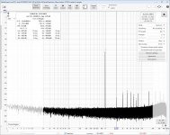
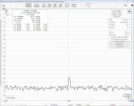
There is one minor "issue" that was probably on the earlier version as well but has now become more apparent. With low input levels (e.g. -60dBFS) the harmonic peaks "pump" slowly up and down by almost 10-15dB. Oddly this pumping happens alternatively either at all even harmonics or att odd harmonics (see attachments 3 and 4 which were taken about 15s apart). Marcel suggested that this is caused by miniscule split in peaks. This may well be the case when looking at 4M FFT zoomed to +-3Hz at 2kHz (second attachment) as there appears to be 2 peaks very close to each other. So the "pumping" is quite likely just a measurement (or FFT) artefact. In my tests all peaks at low levels were at -130dBFS or lower so there should not be much reason for concern regarding audibility.
There is one minor "issue" that was probably on the earlier version as well but has now become more apparent. With low input levels (e.g. -60dBFS) the harmonic peaks "pump" slowly up and down by almost 10-15dB. Oddly this pumping happens alternatively either at all even harmonics or att odd harmonics (see attachments 3 and 4 which were taken about 15s apart). Marcel suggested that this is caused by miniscule split in peaks. This may well be the case when looking at 4M FFT zoomed to +-3Hz at 2kHz (second attachment) as there appears to be 2 peaks very close to each other. So the "pumping" is quite likely just a measurement (or FFT) artefact. In my tests all peaks at low levels were at -130dBFS or lower so there should not be much reason for concern regarding audibility.
Attachments

See section 3.6 of yesterday's updated report. I haven't a clue why the even and odd harmonics alternate.
Marcel,Bohrok2610's measurements from yesterday mainly showed that the approximately 10 kHz component coming out of yesterday's software sigma-delta modulator was not far enough below the 10 kHz component due to intermodulation in the DAC. I've now adjusted it for DSD128 to solve that.
Horizontal scale in Hz, vertical in dB DSD, Hann window, bin size still 100 Hz
Red trace: ideal case
Green trace: some second-order intermodulation introduced by making the bit weight vary +/- 1 ppm depending on the previous bit (I used +/-0.1 % yesterday, but that gave an unrealistically large 10 kHz component)
View attachment 1296548
The source code of the program that generated this spectrum plot, of a program that writes the bit stream to a .dsf file, the .dsf file and the plot are in the attached zip archive.
The purpose of the .dsf file is to hopefully make it easier to simulate or measure differences between the intermodulation products produced by different output filters. I hope it will be of use to Hans and later to myself.
Another attachment is a minor update of the report on the cause of the low-level tones.
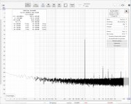
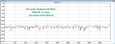
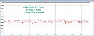
I processed the .dsf file with DC offset, the one that's in your zip file, with two different filters, a fully passive 4th order Butterworth and also the with the original RTZ Firdac filter.
Filter bin was 62.5Hz and simulation step time 0.1nsec.
The passive filter was multiplied by 1.2, but this had to be 2.4 because the passive filter (with Rs = 376.25) attenuated 6dB.
Much to my surprise, both spectra are absolutely identical, but I don't see any intermodulation products.
Any idea why ?
Is it because they are below the noise level in my simulation ?
Hans
Attachments
- Home
- Source & Line
- Digital Line Level
- Return-to-zero shift register FIRDAC