I've been attempting to keep up with the technical discussions but in the background I thought I'd do some practical experiments...🤓
I am really interested in Marcel's idea of a discrete class-A filter board and will certainly be up for trying that out. However in the meantime...
I was interested in trying out the circuits that Bohrok2610 posted using the opa1632 op-amp and so I initially made a pcb design to the original design and tried that out but then once the updated design with the modified filter parameters was presented then I made an updated version to compare that too. Yesterday I fixed my deliberate (haha) mistake on the board and listened to the result. I really like the sound. It has taken the dac to another level for me.

I have a new version uploaded to JLC to fix my errors. This one has options for regs (ie something like LT3045/3094) with the LM317/337 pin-outs. Also mute relays optionally although I've not found them necessary.
This is being tested here on my 2nd DAC which I intend to revamp the power supplies and distribution on. I keep saying that but not quite getting around to it. I have it on the "roadmap" just not got around to it, although I know it could be an easy win and easier than making pcbs but I happen to like making the pcbs. 🤣
If anyone is interested I can put the gerbers up, or indeed the KiCad files.
I am really interested in Marcel's idea of a discrete class-A filter board and will certainly be up for trying that out. However in the meantime...
I was interested in trying out the circuits that Bohrok2610 posted using the opa1632 op-amp and so I initially made a pcb design to the original design and tried that out but then once the updated design with the modified filter parameters was presented then I made an updated version to compare that too. Yesterday I fixed my deliberate (haha) mistake on the board and listened to the result. I really like the sound. It has taken the dac to another level for me.
I have a new version uploaded to JLC to fix my errors. This one has options for regs (ie something like LT3045/3094) with the LM317/337 pin-outs. Also mute relays optionally although I've not found them necessary.
This is being tested here on my 2nd DAC which I intend to revamp the power supplies and distribution on. I keep saying that but not quite getting around to it. I have it on the "roadmap" just not got around to it, although I know it could be an easy win and easier than making pcbs but I happen to like making the pcbs. 🤣
If anyone is interested I can put the gerbers up, or indeed the KiCad files.

The schematic is without the hold time fix,
Right. The schematic was taken from the last KiCad package Marcel posted, but with the test points added. Up to the user to evaluate any instrumentation loading effects. Also, if driving the dac array from external signals, again up to the user to determine appropriate TL damping.
Yet more levels are probably possible, IMHO. Experiments and comparisons with the best I have done so far with Andera Mori dacs gives some cause to believe more is possible. It remains unclear though, exactly how much more can be gotten from Marcel's clever topology.It has taken the dac to another level for me.
Last edited:
Excellent work there and thanks to Bohrok2610 for sharing the design , hopefully others thats built Marcels dac will give it a try .I've been attempting to keep up with the technical discussions but in the background I thought I'd do some practical experiments...🤓
I am really interested in Marcel's idea of a discrete class-A filter board and will certainly be up for trying that out. However in the meantime...
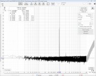
I was interested in trying out the circuits that Bohrok2610 posted using the opa1632 op-amp and so I initially made a pcb design to the original design and tried that out but then once the updated design with the modified filter parameters was presented then I made an updated version to compare that too. Yesterday I fixed my deliberate (haha) mistake on the board and listened to the result. I really like the sound. It has taken the dac to another level for me.
View attachment 1294915
I have a new version uploaded to JLC to fix my errors. This one has options for regs (ie something like LT3045/3094) with the LM317/337 pin-outs. Also mute relays optionally although I've not found them necessary.
This is being tested here on my 2nd DAC which I intend to revamp the power supplies and distribution on. I keep saying that but not quite getting around to it. I have it on the "roadmap" just not got around to it, although I know it could be an easy win and easier than making pcbs but I happen to like making the pcbs. 🤣
If anyone is interested I can put the gerbers up, or indeed the KiCad files.
Last edited:
Right. The schematic was taken from the last KiCad package Marcel posted, but with the test points added.
I've been very lazy: I didn't bother to post an updated KiCad archive after updating the resistor values. I only mentioned in the thread and in post #1 that the values could best be updated.
👍In any case, I intend to make a new filter with more passive filtering before the first active part. It will probably be something largely discrete and operating in class A.
I tested this by changing the 1nF cap to 10nF cap while keeping 8.2nF caps. No change for the better so the improvement in simulation does not seem to carry over to reality.3) The Alternate filter, based on Bohrok's design, has two 10nF caps instead of 8.2nF and 10nF has been added between the two Firdac outlets replacing the 1nF in version 2).
The modulator has more impact on distortions at low level. In addition to quasi-multibit modulators the sox-dsd modulator with 6th order filter at DSD64 performs well even with stock output stage (see attachment).
Attachments
I don’t see any advantage either in the simulation with 3x10nF.
However as it seems, the JRiver conversion that I use for PCM to DSD, also seems to use a similar algorithm as Marcel with his PWM8.
When converting a 44.1 .wav file into a DSD128 .dsf,
HF noise starts at 10Khz.
So with this quasi-multibit it will never show the low level distortion product.
I finally have figured out the right set up for my simulations.
A 1nsec step time was still too large to prevent anomalies from the Firdac’s, so I finally settled at 0.5 nsec.
Since I have only 600GB free space on my disk, I can simulate 16msec max from the DSD128 .dsf file taking 560GB.
That restricts the frequeny bin width to 62.5 Hz, thereby also limiting the minimum noise level.
It will be impossible to get those nice low noise level images that Bohrok produces.
Hans
P.S. every 16msec run takes ca. 4 hours, so I need quite some time to finalise the things on my list and report my findings.
Last edited:
@Hans Polak; Hans a couple of JRiver related questions if I may:
1. Can you set up JRiver so that it automatically converts PCM files to DSD when you play them ?
2. Have you compared JRiver PCM > DSD conversion to PCM2DSD ? If so did you detect any difference In sound quality?
1. Can you set up JRiver so that it automatically converts PCM files to DSD when you play them ?
2. Have you compared JRiver PCM > DSD conversion to PCM2DSD ? If so did you detect any difference In sound quality?
Hi Studley,
1) JRiver can’t convert on the fly while playing.
You have to select a file, instruct JRiver to convert and select to any of the many possibilities.
I used the DSD128 selection.
It takes a minute or so and then your .dsf file apears in the list of files to be played.
2) I don’t have PCMtoDSD but in tests JRiver was rated as one of the very best converters.
Hans
I see no reason why not if both can handle DSD files.
All you have to do is to convert files in advance and they will be available for ever.
Hans
All you have to do is to convert files in advance and they will be available for ever.
Hans
You don't have access to the streamed files for Tidal etc. You could have but thats not the intention and it involves some cheating... I trust you dont subscribe to one? 🙂
//
//
I have a Tidal subsciption but to be honest use it hardly, so I probably misinterpreted the question.
When the question was whether JRiver can play DSD files on the fly either from a local disk or from Tidal, the answer is a full yes.
Hans
When the question was whether JRiver can play DSD files on the fly either from a local disk or from Tidal, the answer is a full yes.
Hans
Do you store all node voltages and branch currents or just the ones you want to take the DFT of?Since I have only 600GB free space on my disk, I can simulate 16msec max from the DSD128 .dsf file taking 560GB.
16 ms/500 ps = 32 000 000, so a few hundreds of megabytes should suffice when you store only a few node voltages - unless the simulator takes a huge number of extra time steps to ensure convergence.
Marcel,
Do you think it makes a lot of sense to look at HD at a particular signal level only when comparing modulators? What about the old stepped DC offset versus noise metric?
I mean, I get that there is interest in minimizing HD coming out of the dac, but does focusing on that to the exclusion of other metrics give a well rounded picture of modulator performance tradeoffs?
For me at least, I know if I only look at HD performance then I start to feel like its the most important consideration, even though I know its only a feeling. IOW, I believe its probably a Focusing Illusion bias.
Beyond that, if we look at all the modulators and filters in HQ Player, they all sound different. Some perform better in time domain transient reproduction, and others look better in the discrete frequency domain view. How best to evaluate those differences?
Last edited:
I think the question was if River was able to convert wav/flac to DSD on the fly...I have a Tidal subsciption but to be honest use it hardly, so I probably misinterpreted the question.
When the question was whether JRiver can play DSD files on the fly either from a local disk or from Tidal, the answer is a full yes.
Hans
Do Tidal send DSD... don't think so... hence the question...
//
Marcel, Good point.Do you store all node voltages and branch currents or just the ones you want to take the DFT of?
16 ms/500 ps = 32 000 000, so a few hundreds of megabytes should suffice when you store only a few node voltages - unless the simulator takes a huge number of extra time steps to ensure convergence.
I will have a look at it and see what settimgs I have.
All that huge data is in a .raw file, but when I delete this file with the LTSpice image still active, I can still make a FFT.
So it seems those 560GB aren’t needed for making an FFT.
Hans
O.k. Now I got it.I think the question was if River was able to convert wav/flac to DSD on the fly...
Do Tidal send DSD... don't think so... hence the question...
//
Thx for making this clear.
Hans
- Home
- Source & Line
- Digital Line Level
- Return-to-zero shift register FIRDAC