It's something like that, yes. 378.75 ohm is my estimate including shift register internal resistance.
Till now I have been used a 4rt order butterworth low pass filter at 30kHz.
What version FPGA code did you load? There are versions by at least three different people. Depending which one you are using that might affect the filter cutoff frequency.
In my case, I have performed listening tests to the stepup trafo, in order to properly load it.
Back then when I listen analog straight from DSD2pcm output.
Was a long jouney, guessing in first a 50 ohm as a source standard, I do the math and expect 2k, but to be conservative I placed in the secondary a fixed 1k5 + 1k pot settled to half (500R)
So from the start the sound was pleasant. I could'nt turn neither up or dawn without degrade.
Later on I changed the setting for a more convenient finetune, and placed a fixed resistor 1950 + a 100R pot. setlled at half (50R).
Start listening again, the best sound 2020ohm but noticed bellow the teansformers the manufacturer placed 200k SMD resistor, I do the parallel resistor math and result 2k ohm total resistor.
Now I noticed a mistake in the math. Having a 2k load resiistor, actually results 47,3 ohm RTZ FirDac impedance 2000÷ 6,5^2
Note:
Forget to mention, after the Firdac install, I repeated the fine tune of the rload, and barely changes 2 or 3 ohm. So about the same.
Last edited:
Hi Mark, is late here in Catalonia, lets see tomorrow I must search in first for what akronim FPGA stand for😬What version FPGA code did you load? There are versions by at least three different people. Depending which one you are using that might affect the filter cutoff frequency.
Are you using PCM2DSD, or maybe HQ Player, or what do you use to convert PCM to DSD?lets see tomorrow I must search in first for what akronim FPGA stand for😬
@JOIMONF : Hi ... just FYI (in case it may be relevant to you) HQPlayer's noise level doesn't start increasing until appr. 55 - 60 kHz (at DSD128 - moves upward with higher sampling frequency).
I personally have chosen to place my filter cut-off frequency a bit higher and accept a slightly elevated HF noise floor in return for a cut-off frequency that is "well" (?) outside of the audible frequency range. I have, however, not been experimenting much with finding an optimum cutoff frequency but do remember that increasing the frequency from (to my memory) ~80 kHz to ~93 kHz made an audibly positive difference (more air and "complete" sound).
Just my findings in my setup 😉
Cheers, Jesper
doesn't start increasing until appr. 55 - 60 kHz (at DSD128
Doesn't that depend on which of the many modulators you choose?
Hi Marcel ... well, this is to my memory - but as I expected different responses from the different algorithms, I remember somewhat actively noticing being surprised that this was not really the case. The responses were quite similar both wrt noise and distortion for the algorithms I tried.Doesn't that depend on which of the many modulators you choose?
That said I would like to also say that I have only tried 3 or 4 modulators - one for listening, and two or three for measurement purposes (it was/is my impression that the modulator(s) most preferred SQ-wise by people active in the audiophilestyle.com HQPlayer thread (https://audiophilestyle.com/forums/topic/19715-hq-player/) are the later ones (ASDM7ECv2 etc.) and - without delving deep into this - this has also been my conclusion).
Besides the ASDM7ECv2 for listening, the ones I used for measurement purposes have been e.g. DSD5 and DSD5v2 since they require much less computer processing power (to my ears their SQ is lesser, though).
A bit surprising to me that this is what I measured, but I checked the setup several times to make sure I had not made an error somewhere, and it did not appear to be the case ...
Cheers, Jesper
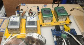
Concerning for Dac impedance, I had also adjusted the Rload for another step up transformer the green pair one on pic. right side. A 8X gain in this case.

I spent time tuning and finetuning (it pay dividents juicing the precision at extreme), end up with 3093 Ohm for best sound. Allright, the 8X stepup has Rload. Math: Rin (source impedance) = Load resistor (Rout)÷ X (amplification ratio)^2 = 3093 ÷ 64 = 48,3 Ohm. All in all before add Firdac, but as said yesterday, not seen much difference thereafter. I tought back at the time, the Firdac performs good at maintaining the integrity of the weak digital signal. As it does my passive filter, I got it specified to maintain the impedance.

I spent time tuning and finetuning (it pay dividents juicing the precision at extreme), end up with 3093 Ohm for best sound. Allright, the 8X stepup has Rload. Math: Rin (source impedance) = Load resistor (Rout)÷ X (amplification ratio)^2 = 3093 ÷ 64 = 48,3 Ohm. All in all before add Firdac, but as said yesterday, not seen much difference thereafter. I tought back at the time, the Firdac performs good at maintaining the integrity of the weak digital signal. As it does my passive filter, I got it specified to maintain the impedance.
Source impedance is 378x2, primary impedance of the transformer is 48ohm, gain 8x,
Total gain after transformer is around 1/2 of direct balance output from shift register.
This level is same as single end passive output.
Also you need buffer after transformer output, as 3K is too high to drive the IC and next stage.
Total gain after transformer is around 1/2 of direct balance output from shift register.
This level is same as single end passive output.
Also you need buffer after transformer output, as 3K is too high to drive the IC and next stage.
48 ohm sounds like a good virtual ground, compared to the 757.5 ohm (differential) source. When the DAC is loaded with a (differential) virtual ground, that helps to keep data-dependent currents out of the reference supply small.
Just my experience for another dac project with transformer output.
Recently used BEHRINGER UCA202 with REW to test the frequency response of Bisesik D60 transformer (1:16), the curve is almost flat (actually -0.5db down from 9k to 16k) when source load resistor is dropped to 20ohm. Ivan suggested loading at the source is better than at secondary.
Recently used BEHRINGER UCA202 with REW to test the frequency response of Bisesik D60 transformer (1:16), the curve is almost flat (actually -0.5db down from 9k to 16k) when source load resistor is dropped to 20ohm. Ivan suggested loading at the source is better than at secondary.
@2A3SET sure is worth to mention here as a caveat, agree it is a high impedance output at 2K (using a 6,5X stepup.)
Buy not appliable in my case, after the Dac I have LDR volume control, which has buffer isolation hability. Let me set a wide range of values in long calibration cicles both for nominal impedance and load impedance. I use it splitted from preamp and placed close to DAC.
Buy not appliable in my case, after the Dac I have LDR volume control, which has buffer isolation hability. Let me set a wide range of values in long calibration cicles both for nominal impedance and load impedance. I use it splitted from preamp and placed close to DAC.
Don't have an exact answer. You might try 60kHz or so and see what you think. Its just that there is never perfect filtering, and filter components can go through self-resonance effects and impedance variations when higher frequency RF is present.Pease lets me know how much higher can I pick the cutoff frequency.
I filtered today 100kHz (DSD128) and still did'nt notice any issue. To the contrary, due to reduced inductance an capacitance (vs. filter at 75kHz cutout) , I listened an important upgrade to sound. Better slam/weigh bass together with much warmer and creamy timbre for high freq.
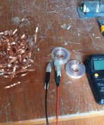
Here is foto peeling off copper turns to reduce inductance from a 0,5mH coil (now spare) to needed 0,15mH.

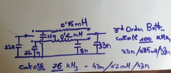
One channel schematic with two diferent filters with 2 switches to allow listening comparison without variables and "on the fly".

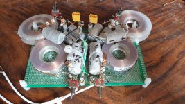
Stereo with 4 switches, easy to swap cutout 76/ 100 kHz

By the way, I simulated values for a 47 ohm Firdac impedance Out.
I do not further increase the cutout before upgrade to DSD256. Hope to receive the Xilinx soon.
Here is foto peeling off copper turns to reduce inductance from a 0,5mH coil (now spare) to needed 0,15mH.

One channel schematic with two diferent filters with 2 switches to allow listening comparison without variables and "on the fly".

Stereo with 4 switches, easy to swap cutout 76/ 100 kHz

By the way, I simulated values for a 47 ohm Firdac impedance Out.
I do not further increase the cutout before upgrade to DSD256. Hope to receive the Xilinx soon.
Last edited:
Hello
Does any colleague have a PCB of the latest version of the RTZ DAC for resale or can point out where I can buy this PCB ?
If anyone would be interested I have a few pieces of PCM2DSD
Does any colleague have a PCB of the latest version of the RTZ DAC for resale or can point out where I can buy this PCB ?
If anyone would be interested I have a few pieces of PCM2DSD
- Home
- Source & Line
- Digital Line Level
- Return-to-zero shift register FIRDAC