That probably explains why Thorsten only got 20 dB of improvement.
Marcel, all my applications have been "single point error nulling", that is a feedback circuit is connected to the point where the error manifests and uses ultimately negative feedback to reduce the Error. So no special trimming in most cases.
I have done this for a wide range of different systems and items, from Poweramplifier's feedback loops (variant of Sandman Error take-off), around two decades ago, to power supplies and even AC mains.
Usually the systems are lowish impedance and relatively well engineered from the start. So there limits to improvements and anything below AP2 residue I consider not worth chasing.
As my designs were commercial, cost was an issue and NJM5534 is usually my choice of error amplifier (because of accessible internal nodes not available on other IC's), which limits performance further.
Thor
It would do multiple things. It would slow risetime, delay the clock pulse, and result in increased reflections. Whatever it does, so long as our end goal is to satisfy the human auditory perceptual system rather than to satisfy the visual system with a nice looking skirt, I would argue that we should do whatever best meets the end goal. Of course if we set out to build a measurement system then the end goal would be different....it would indicate that the 100 ohm resistor caused more close-in phase noise in the circuitry...
The reason I say the above is because there are still so many things we don't understand about how brains process sound. There are also technical things we don't really understand as well as we may believe, such as cables. Why mention cables as an example? Because superficially they seem quite simple, yet for those people who can hear differences in cables it is obvious that cables are more complex than the superficial models would suggest.

IMO cabling is critical, not necessarily or solely of themselves causing issues, rather also impacting on the variant manner of being driven or in being received. It also seems that as systems are becoming increasingly resolved there seems no escaping balanced interconnecting lines.
What I find concerning is the high resistance values often used in the output of amplifiers or preamplifiers. If one considers dielectric materials as "potentially" masking sonics (trying not to ruffle the feathers of the mass nay sayers too much) it is considered that output impedances reduced to zero ohms drives signals to the opposing end regardless of capacitance value or dielectric effects. This simply concludes that electrons lost in the material are replaced or those returning become sunk. The issue is that many output networks or devices become unstable or are marginally so.
What I find concerning is the high resistance values often used in the output of amplifiers or preamplifiers. If one considers dielectric materials as "potentially" masking sonics (trying not to ruffle the feathers of the mass nay sayers too much) it is considered that output impedances reduced to zero ohms drives signals to the opposing end regardless of capacitance value or dielectric effects. This simply concludes that electrons lost in the material are replaced or those returning become sunk. The issue is that many output networks or devices become unstable or are marginally so.
What makes you think there is only one issue?The issue is that many output networks or devices become unstable or are marginally so.
Didn't mean to imply there was. When things get refined enough It is mostly guess work isn't it?
It's time to continue the technical distraction I started in post #2080 about elevated distortion at 10kHz. I have now tested some of the output stages proposed in this thread.
But before delving into that output stage shootout first a couple of posts on some subtle but possibly more important issues related to RTZ dac.
WARNING: following posts contain images of PSS FFT measurements. Some people may find such images disturbing or offensive. Reader discretion is advised.
But before delving into that output stage shootout first a couple of posts on some subtle but possibly more important issues related to RTZ dac.
WARNING: following posts contain images of PSS FFT measurements. Some people may find such images disturbing or offensive. Reader discretion is advised.
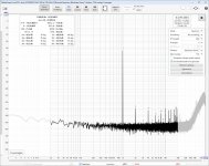
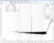
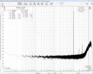
Some time ago I noticed that Marcel's RTZ dac has quite a bit of distortion at low levels.
E.g. here is 1k -60dBFS with PCM2DSD (host -> USB-I2S -> PCM2DSD -> RTZ).

Further testing showed that this distortion has frequency dependency. I.e. it is pronounced between 500Hz to 3kHz. First I assumed this has something to do with PCM2DSD but the same setup with AK4493 (host -> USB-I2S -> PCM2DSD -> AK4493) resulted in immaculate FFT.

This lead me to test various alternatives: output stage, Vref, (re-)clocking, psu. But to no avail. It seemed that low level distortions are somehow intrinsic to the design. Marcel pointed out that other modulators than plain single-bit modulators would work better and that turned out to be true. More about that on next post.
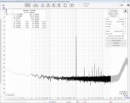
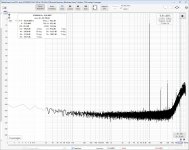
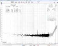
Back to PCM2DSD. At some stage I noticed that the distortion number and FFT peaks in (picture) did not match. Also the distortion indicator numbers where not on top of peaks as they should be.

Zooming in on one of the peaks revealed this:

So in addition to the harmonic distortion peak there are additional peaks at about 1 Hz apart. Same occurs on all harmonics. Marcel promptly suggested that this is probably due to a small digital DC offset. I tested this by adding "artificial" digital offset to PCM samples at USB-I2S which indeed produced similar splitted peaks. I also verified that without PCM2DSD, i.e. using DSD output from USB-I2S directly, there were no splitted peaks. So PCM2DSD seems to be the culprit.
I have notified PCM2DSD developers about this possible DC offset. It probably does not impact NRZ dacs so it has gone unnoticed. But hopefully they can come up with a fix.
E.g. here is 1k -60dBFS with PCM2DSD (host -> USB-I2S -> PCM2DSD -> RTZ).
Further testing showed that this distortion has frequency dependency. I.e. it is pronounced between 500Hz to 3kHz. First I assumed this has something to do with PCM2DSD but the same setup with AK4493 (host -> USB-I2S -> PCM2DSD -> AK4493) resulted in immaculate FFT.
This lead me to test various alternatives: output stage, Vref, (re-)clocking, psu. But to no avail. It seemed that low level distortions are somehow intrinsic to the design. Marcel pointed out that other modulators than plain single-bit modulators would work better and that turned out to be true. More about that on next post.
Back to PCM2DSD. At some stage I noticed that the distortion number and FFT peaks in (picture) did not match. Also the distortion indicator numbers where not on top of peaks as they should be.
Zooming in on one of the peaks revealed this:
So in addition to the harmonic distortion peak there are additional peaks at about 1 Hz apart. Same occurs on all harmonics. Marcel promptly suggested that this is probably due to a small digital DC offset. I tested this by adding "artificial" digital offset to PCM samples at USB-I2S which indeed produced similar splitted peaks. I also verified that without PCM2DSD, i.e. using DSD output from USB-I2S directly, there were no splitted peaks. So PCM2DSD seems to be the culprit.
I have notified PCM2DSD developers about this possible DC offset. It probably does not impact NRZ dacs so it has gone unnoticed. But hopefully they can come up with a fix.
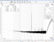
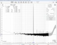
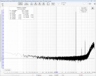
As mentioned in my previous post this RTZ dac seems to have somewhat pronounced distortions at low levels. This is probably related to additional FM-like tones generated by the modulator. Marcel has a plausible theory on this but I leave it up to him to explain it in detail.
This issue has a clear dependency on the modulator. Different modulators produce different levels of distortion. To test this I generated test signals with sox. First to to PCM format and then converted to DSD format using sox-dsd with sdm-8 filter. Here are distortions with DSD128 at -40dBFS, -50dBFS and -60dBFS using HQPlayer's "ASDM7EC-light" modulator.
Although distortions are higher than e.g. with AK4493 these are most probably not audible. So this is mostly an "academic" issue.
Attachments

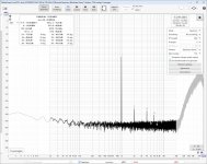
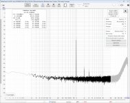
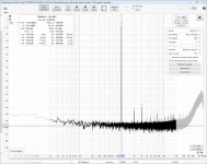
Anyhow according to Marcel properly dithered quasi multibit modulators just produce shaped noise so they should have lower distortions at low levels. Here are same measurements but with HQPlayer's "AMSDM7 512+fs" modulator.
Distortions are clearly lower especially at -60dBFS.
So it seems quasi multibit modulators work better with this RTZ dac. Those who use HQPlayer should try AMSDM7 modulator. However it is computationally more complex so online conversions from PCM to DSD256 or higher require a top-notch computer.
Distortions are clearly lower especially at -60dBFS.
So it seems quasi multibit modulators work better with this RTZ dac. Those who use HQPlayer should try AMSDM7 modulator. However it is computationally more complex so online conversions from PCM to DSD256 or higher require a top-notch computer.
Attachments
Last edited:
Back to the output stage shootout.
For this test I made 4 output stage "hats" that could be fitted to my main RTZ board.
This is the lineup:
1. stock
Although I made a "hat" for this as well I run out of components so stock output stage in this test is the R-channel on the main RTZ board. Other output stages are fitted as hats to L-channel on the main RTZ board. In theory this should give stock filter a more optimal layout with better ground planes.
2. ThorstenL's suggestion (based on Birt)
This output stage is based on what ThorstenL simulated in post #2150 although without the passive input filter.
Here is the schematic.

3. Dual OPA1632
This is more or less what I tested in post #2148 but modified to have same filter characteristics as stock.
Here is the schematic.

4. OPA1632 + OPA1678
Basically the same as 3. but with OPA1678 as second stage. I included this to test Marcel's second-stage-distortion hypothesis.
Here is the schematic.

All output stage hats were implemented as 4-layer boards. Passive components were matched to 1% or better.
The test setup was this:
Player: HQPlayer 5.5.1 running on battery powered laptop. Output format set to DoP.
USB-I2S: my STM32H723 board
ADC: my ES9822PRO board
I2S-USB: same as USB-I2S
Test signals used in this test were these:
10kHz at 44100Hz -3dbFS
1kHz at 44100Hz -3dBFS
1kHz at 44100Hz -60dBFS
Test signals were generated with sox in the same fashion as in my previous post. I used DSD128 bit rate.
Modulator used in HQPlayer was ASDM7EC-light.
For this test I made 4 output stage "hats" that could be fitted to my main RTZ board.
This is the lineup:
1. stock
Although I made a "hat" for this as well I run out of components so stock output stage in this test is the R-channel on the main RTZ board. Other output stages are fitted as hats to L-channel on the main RTZ board. In theory this should give stock filter a more optimal layout with better ground planes.
2. ThorstenL's suggestion (based on Birt)
This output stage is based on what ThorstenL simulated in post #2150 although without the passive input filter.
Here is the schematic.
3. Dual OPA1632
This is more or less what I tested in post #2148 but modified to have same filter characteristics as stock.
Here is the schematic.
4. OPA1632 + OPA1678
Basically the same as 3. but with OPA1678 as second stage. I included this to test Marcel's second-stage-distortion hypothesis.
Here is the schematic.
All output stage hats were implemented as 4-layer boards. Passive components were matched to 1% or better.
The test setup was this:
Player: HQPlayer 5.5.1 running on battery powered laptop. Output format set to DoP.
USB-I2S: my STM32H723 board
ADC: my ES9822PRO board
I2S-USB: same as USB-I2S
Test signals used in this test were these:
10kHz at 44100Hz -3dbFS
1kHz at 44100Hz -3dBFS
1kHz at 44100Hz -60dBFS
Test signals were generated with sox in the same fashion as in my previous post. I used DSD128 bit rate.
Modulator used in HQPlayer was ASDM7EC-light.


Based on this test dual OPA1632 has lowest distortions at 10kHz. The 4th filter with OPA1678 as second stage was clearly worse than dual OPA1632. This seems to support Marcel's second-stage-distortion hypothesis. Also filters 3 and 4 had more passive filtering before the first opamp. Adding passive filtering as ThorstenL suggested to stock or Thor's filter would very likely improve those filters as well.
At 1kHz differences were much smaller.
At 1kHz differences were much smaller.
Excellent work huge thanks for sharing ! This’ll give us plenty to read through and digest . Would these latest filter values for the dual opa1632 stage offer any benefit over the original circuit you posted ?
The original circuit is from my AK4493 dac which I also use for measurements so it has much higher cutoff than the dual OPA1632 filter stage in this test. The latter also has a steeper filter. So for RTZ dac it is better to use the dual OPA1632 stage in this test.
Very nice (and loads of) work.
If I can abuse your work, I had assembled this table about slew rates:
Slew rate of the parts in testing:
OPA2210 - 6V/usec
OPA1678 - 9V/usec
OPA1612 - 27V/usec
OPA1632 - 72V/usec
So it seems that in this specific dac, without extra passive filtering introduced, the minimum required slew rate to avoid SID floats around 70V/usec.
It sounds quite probable that this limit depends on the actual quantity and distribution of noise energy as generated by the dac. Like in a CS4398 & multibit output stage it was lower enough to permit the use of OPA1612 with already sufficient result.
Kudos are due @bohrok2610 - very impressive and interesting work! ... And also thanks for sharing. Pondering time 😉
Cheers, Jesper
Cheers, Jesper
- Home
- Source & Line
- Digital Line Level
- Return-to-zero shift register FIRDAC