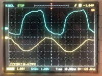
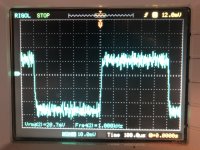
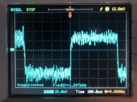
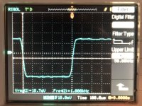
IMO the issues seem critical with IM, specifically as related to rectification issues of the kind being tested specific to EMI/RFI. In this regard the four screenshots show a mechanism of testing my own I/V involving feeding two capacitance coupled summed signals feeding the inverting input of the I/V. The upper trace (ignore bottom waveform) in the first screenshot is a ~17MHz wave ~+/-3V pk/pk waveform capacitance coupled signal feeding into a 1.5 KOhm resistor causing ~+/- 1mA to flow to the inverting terminal. This is combined with a 1KHz square wave ~+/-0.4V pk/pk waveform (not shown) capacitance coupled signal feeding into a 200 KOhm resistor causing ~+/- 1uA to flow to the inverting terminal. The feedback is filtered at about 150KHz being fed to a 10x amplifier with some further filtering. The second screenshot is absent of the 17MHz signal, the third is with the 17MHz, and the fourth with digital filtering applied by the oscilloscope set to 50KHz.
What is important IMO is that the network is DC coupled beyond the input (for testing purposes), whereupon DC shifting is the result of rectification showing up between screenshot 2 and 3, corresponding to <1mV (barely visible but measured on a multimeter) for a 60dB increase in high frequency current. Further that subsequent filtering, although can be much cleaner, cannot remove IM products created prior to it. This is to state that adding subsequent filtering may look cleaner but adding further networks might only deteriorate sonics without benefit, that IMO often does.


What is important IMO is that the network is DC coupled beyond the input (for testing purposes), whereupon DC shifting is the result of rectification showing up between screenshot 2 and 3, corresponding to <1mV (barely visible but measured on a multimeter) for a 60dB increase in high frequency current. Further that subsequent filtering, although can be much cleaner, cannot remove IM products created prior to it. This is to state that adding subsequent filtering may look cleaner but adding further networks might only deteriorate sonics without benefit, that IMO often does.


Last edited:
Using Amanero means no galvanic isolation of USB.
Galvanic isolation is generally overrated.
Most of the caps are Rubycon:
These are nice. I tend to use similar ones from Panasonic. Need to try these.
The stuff about opamps and filtering was known years ago by Allo and me.
I remember debating this in the 1990's... Yes, it is a very old hat.
There are tradeoffs with filtering before I/V stage however, but probably more so with CMOS dac ICs since the internal resistors are so nonlinear.
Commonly CMOS IC's use current sources or switched capacitors, resistor based DAC's are pretty rare.
John Westlake also talked about Little Logic and using the smallest SMD packages to minimize inductance.
Again, it's an old hat. But back when we were running 16 Bit at 44.1kHz with 1.4MHz bit clocks it was not all that much of a problem. Now running at 22.58MHz it is.
Andrea Mori has a version of a RTZ DSD dac that goes +1 and -1 with 0 in the middle.
Interesting. I came to the same solution.
Doesn't swing a lot of volts though.
Best logic I can find for the bit switch job is rated for +/-3V absolute max. Long way short of 30V.
Turns out very many things are audible. They can all be measured to varying extents, but the numbers may sometimes be small-ish.
things like noise floor rise in FFT or rising HD spurs in FFT are the visible symptoms, they are not the actual problem.
So, having Thor here, a technical guy with ears, is kind of refreshing for me.
I expect it may be more productive if we talk in DM's. Matthaeus 13:14 and onwards.
Thor
True, but it tends help some. There is also radiated junk that jumps across the galvanic barrier. Also interesting, some in-line USB isolators can make the USB noise problems worse.Galvanic isolation is generally overrated.
True.things like noise floor rise in FFT or rising HD spurs in FFT are the visible symptoms, they are not the actual problem.
Might be 🙂...it may be more productive if we talk in DM's.
Last edited:
yes, very.Is he serious?
Possibly, but typically only Jiles-Atherton type models for a periodic waveform and not a Preisach model with infinite memory which tends to make the interaction with non periodic audio signal rather complex.In magnetics for SMPS all he writes about is well defined.
yes. also trafos for electrostatics must be suspected. Also the soft parts in a speaker driver show mechanical hysteresis.Any tube amplifier has hysteresis in the output transformer. As has any Microphone transformer.
it was not the intent to be that takeaway from the blog post. it’s a common problem for class D and speaker drivers.How come it only causes problems in the output of a Class D Amplifier?
https://purifi-audio.com/blog/tech-notes-1/this-thing-we-have-about-hysteresis-distortion-3
yes, goes away if the iron is far away from the coil/conductor. But some ribbons use a step down trafo and here the iron comes back typically. Low inductance is better than high since the generated field is smaller with low inductance. Shorting the field with copper helps.The problem is absent with planar tweeters, IME, but very strong with low inductance dome tweeters.
cheers,
Lars
lrisbo:
Possibly, but typically only Jiles-Atherton type models for a periodic waveform and not a Preisach model with infinite memory which tends to make the interaction with non periodic audio signal rather complex.In magnetics for SMPS all he writes about is well defined.
That was not my exact point. Hysteresis in magnetics is documented for a century and Ferrite material datasheets contain a lot of information.
My experience is that with correct choice of material and geometry, added distortion in the audio range for ferrite cored inductors is ephemeral. Predictably that mans choosing the most linear material, with a significant airgap making the resulting inductor relatively large and expensive.
Distortion in the output inductors of Class D amplifiers is also documented from early days.
Mitigation strategies are also documented and patented.
Yet it is presented as if suddenly the light went on on the road to Damascus. That is the point of my comment "Is he serious" on the "amazing discovery" of something hidden in plain sight and reasonably expected to be known to those skilled in the art as something everyone is too much of an idiot to know about.
All models are reductions of the real to a certain point that ensures they are adequate for the intended purpose. To complain they are not good at something beyond their scope. Nevertheless, selecting ferrites according the classic models for low distortion will give low distortion.
lrisbo:
yes. also trafos for electrostatics must be suspected. Also the soft parts in a speaker driver show mechanical hysteresis.Any tube amplifier has hysteresis in the output transformer. As has any Microphone transformer.
Let's not forget magnetic steel leads in passives and capacitor dielectrics.
YET, despite hysteresis in Tube Amplifiers and step-up transformers in electrostatic speakers such systems are often considered some of the most resolving and musical among the cognoscenti. How can we reconcile this?
lrisbo:
it was not the intent to be that takeaway from the blog post. it’s a common problem for class D and speaker drivers.
Hysteresis is a common problem wherever magetics are involved.
In the 1930's German engineers invented the use of RF bias for magnetic tape to overcome this, so the voice of the Fuehrer could be recorded and replayed with fidelity large enough to fool listeners into believing he was speaking live.
lrisbo:
some ribbons use a step down trafo and here the iron comes back typically.
Hence my note "magnetic planers", which do not.lrisbo:some ribbons use a step down trafo and here the iron comes back typically.
lrisbo:
Low inductance is better than high since the generated field is smaller with low inductance. Shorting the field with copper helps.
Surely the field is dependent on number of turns and current. With low inductance the current is higher. Let us presume the number of turns is identical.
However, all this detail is not needed here.
The question remains why it took decades of selling flawed Class D amplifiers with the evil hysteresis distortion to unsuspecting punters as sine qua non, when this problem is documented and known for likely a century and why such an old hat is elevated to a new discovery and cause celebre?
In other words, "Is this more than a cynical and obvious marketing ploy?
Thor
I had a closer look at your posting #1929.The noise in Hans's plots is quite likely caused by Amanero as there is no such noise apparent with my USB-I2S board.
E.g. in post #1929
My RTZ board has DCLK reclocking which is essential for these dacs to get good SNR.
Very impressive results and not a shade of the nasty equidistant peaks that I had.
It even seems that the level you recorded is the same as with the 55h dsf file that Marcel produced.
Amanero is simply not on par to combine with Marcel’s design.
It’s a pitty I didn’t have the USB-I2S converter.
Hans
Maybe PCM needs some high frequency injection bias.... to get rid of all the hysteresis in those steel leaded metal film resistors, etc. I might try it.Hysteresis is a common problem wherever magnetics are involved.
In the 1930's German engineers invented the use of RF bias for magnetic tape to overcome this...
In the past I have experimented with (moderately) high frequency injection in some power amplifiers. There is some sonic benefit in the feeling of presence and coherency, though not outweighing negatives that I can't recall the nature of anymore.
Regarding interleaving:
One might be inclined to take a DSDn file and split up the bitstream over k interleaved DACs (where k is some integer greater than 1) of which the outputs are added, and to do the splitting by sending the first bit to the first DAC, the second bit to the second DAC ... the kth bit to the kth DAC and then start over again with the first DAC. For example, start with DSD512, use four DACs running at a DSD128 rate but with a clock phase shift between them, and send bits 1, 5, 9, 13... to the first DAC, bits 2, 6, 10, 14... to the second DAC, bits 3, 7, 11, 15... to the third DAC and bits 4, 8, 12, 16... to the fourth DAC.
This has one big disadvantage: you get very tough matching requirements between the DACs. Splitting the bitstream like this is basically decimating without decimation filter, causing the quantization noise around fs/4 and fs/2 to alias on top of the audio band. When the output signals of the four DACs are added in exactly the right proportions, the aliased noise cancels. With a slight mismatch in amplitude or a slight phase error, it won't - not completely anyway.
When you let all DACs (which in my circuit means all shift register taps) convert all bits, there is no decimation and this issue doesn't occur. Tap mismatch then only reduces the stopband suppression of the FIRDAC, making matching far less critical.
Simply can't recall the sonic problems that caused me to give it up. Perhaps an irregular coarseness with the presence. It was a long time ago. Perhaps even some (inter)modulation issues. The amplifier wasn't that good by todays standards.
This does seem connected to the thread in that the FIRDAC can be considered an RF bias modulator of sorts. Maybe thats why the sonics works.
This does seem connected to the thread in that the FIRDAC can be considered an RF bias modulator of sorts. Maybe thats why the sonics works.
Last edited:
Thor,In other words, "Is this more than a cynical and obvious marketing ploy?
I don't know the answer to your question, but I do know that a lot of people in the forum up until Bruno posted that didn't believe hysteresis distortion was a real thing, and if it was real, they didn't believe it could be audible to anyone.
Similar thing for something that @lrisbo posted in their blog about common audio FFTs where phase information is discarded:
https://purifi-audio.com/blog/tech-notes-1/doppler-distortion-vs-imd-7
Unfortunately it looks like the example files have gone missing. The point it shows is that phase can matter to human perception. Okay, yes, it is an example of phase shift that exceeds the threshold of audibility for group delay. Thus there is a change in an amplitude envelope that is audible (also, even FM modulation is possible). The blog post got a lot of people around here thinking about that fact relative phase can be audible.
And, yes, of course, once these sorts of things are well understood then they seem obvious. However, such things still may not be obvious to a lot of people in various audio forums.
Rather, a lot of people still believe that HD/THD and noise floor are all there are; and that human hearing is a phase-insensitive FFT analyzer. Didn't Helmholtz promote that very idea in his formulation of Ohm's acoustical law?
Thus, I applaud Bruno and Lars for trying to enlighten folks who hold some popular but not quite right beliefs about audio and or human perception. Bruno has a long history of trying to teach, too. I don't see it as all being cynical. IMHO, its was needed. Someone of stature needed to talk about those things.
Last edited:
Dear Hans@THOR,
Your last postings have absolutely nothing to do with the subject of this thread.
Please start you own thread where you can ventilate your enormous wisdom.
Hans
Bruno's article wasn't brought up here by Thor.
As for the value of it's content, most of us here were in agreement about it when the issue first appeared, remember? ("The Black Hole..." April-May 2020)
George
@Markw4 : Mark .. with reference to your posts #2342 & #2354 do you have any idea why this could be so?
https://www.diyaudio.com/community/...-register-firdac.379406/page-118#post-7624395
https://www.diyaudio.com/community/...-register-firdac.379406/page-118#post-7624568
My own listening on a NoDAC DSD suggests something similar regarding the (slight) thinness but why may/might it be so?
I have been thinking component sonic signatures, however, when I measure the NoDAC the distortion increases slightly at lower frequencies (80 Hz) and includes more harmonics whereas e.g. a 10 kHz spectrum is very clean indeed. Might it be that - for some reason - the low(er) frequencies may be reproduced "less optimally" by the DSD conversion structure as such - and thus this causes a perceptually perceived "thinness" to be the effect?
I have been thinking that although maybe from a theoretical point of view the DSD conversion works at a high clock frequency - and thus should have no issues with low frequency reproduction (?) - then the return currents going back into the PSU filter components of the DAC logic ICs essentially would be audio frequency return currents ... And the components typically used to filter these logic ICs are ceramic capacitors - in the case of Marcel's RTZ DAC, a 22 uF X7R capacitor. Such components exhibit a quite rising low frequency impedance and thus might not be able to "dynamically" accept these "lower frequency" return currents ...
Just a thought - but if there is such a thinness then I reckon there would somehow be a reason for it?
Cheers, Jesper
Dear George,Dear Hans
Bruno's article wasn't brought up here by Thor.
As for the value of it's content, most of us here were in agreement about it when the issue first appeared, remember? ("The Black Hole..." April-May 2020)
George
True, it was mentioned only as a very short side note at the end in #2392 by Mark.
But then it triggered a series of reactions far outside the scope of this thread.
Hans
I don't know the answer to your question, but I do know that a lot of people in the forum up until Bruno posted that didn't believe hysteresis distortion was a real thing, and if it was real, they didn't believe it could be audible to anyone.
Seriously? What is the world coming to, when simple and obvious points are ignored.
I remember NWAV guy documenting distortion in ferrites back in 2011...
2-17 STABILITY (one myth confirmed)
Audiophiles claim at least some output inductors sound bad and there just might be something to that. I tried at least half a dozen different inductors in the output of the QRV09 trying to get rid of the datasheet mandated 10 ohm resistor for the TPA6120 and it didn’t go well. All the ferrite inductors significantly increased distortion.
https://nwavguy.blogspot.com/2011/07/o2-design-process.html
Early iFi headphone amplifiers embedded a planar output inductor in the PCB, until I spend the time to find the lowest distortion inductors from preferred suppliers AND started using multiloop differential nested feedback loops, with the main audio band one including the inductor. At that point it became a nonissue.
And, yes, of course, once these sorts of things are well understood then they seem obvious.
I remember most of them well understood before I was born and unlike my GF, I ain't exactly a spring chicken.
However, such things still may not be obvious to a lot of people in various audio forums.
Maybe the EE101 remedial I often suggested in discussions decades ago (to the chagrin of those on the receiving end of the honest and straightforward recommendation) could help, but I stopped suggesting it when I noticed that people took it as grave insult.
Someone of stature needed to talk about those things.
Probably. And Ideally someone like Omar Hawkesford, who is academia and not someone flogging the fifth warm over of a Philips designed Amp with the article.
Anyway, I'll shut up and let the thread return to the main debate.
Thor
One might be inclined to take a DSDn file and split up the bitstream over k interleaved DACs (where k is some integer greater than 1) of which the outputs are added, and to do the splitting by sending the first bit to the first DAC, the second bit to the second DAC ... the kth bit to the kth DAC and then start over again with the first DAC. For example, start with DSD512, use four DACs running at a DSD128 rate but with a clock phase shift between them, and send bits 1, 5, 9, 13... to the first DAC, bits 2, 6, 10, 14... to the second DAC, bits 3, 7, 11, 15... to the third DAC and bits 4, 8, 12, 16... to the fourth DAC.
That does not work well.
BUT if we have a DSD2048 system clock and produce 4 DSD512 streams in effect as 4 Bit multibit modulator that are offset for bit transition by 1 DSD2048 clock, we have an interleaved system with reduced switching residue that sits at DSD2048 and system that de facto is interleaved to produce (or re-produce) DSD2048 by interleaving four DSD512 DAC's.
This has one big disadvantage: you get very tough matching requirements between the DACs. Splitting the bitstream like this is basically decimating without decimation filter, causing the quantization noise around fs/4 and fs/2 to alias on top of the audio band. When the output signals of the four DACs are added in exactly the right proportions, the aliased noise cancels. With a slight mismatch in amplitude or a slight phase error, it won't - not completely anyway.
It cancels well enough in practice with 0.05% resistors. But it still doesn't work well, at least not the way I tried.
Thor
- Home
- Source & Line
- Digital Line Level
- Return-to-zero shift register FIRDAC