Ok, I understand. It is possible that DCLK in my case has too much jitter for RTZ dac which is the reason for the elevated noisefloor. DS dacs (ES9038Q2M or AK449x) may well be more tolerant to DCLK jitter.So what seems to be jitter, are the L and S periods in between, but Marcel explained that this has no effect on the Dac.
Understood. However, for Andrea's FIRDAC (which has more taps than yours), listening tests show best subjective SQ with 5/6MHz oscillators and two doublers. Could it be Andrea's clocks are highly symmetrical over time so that doubling as a practical matter tends to have less that the worst case effects? Maybe deeper notches from more taps can help? Could also be that other dynamic problems with data conversion may tend to mask any remaining effects of clock doubling? The point I am trying to get it at is there are things we may not fully know about in practice, yet we have some empirical evidence that what Andrea is doing with his dac seems to be working well.The issue with clock doublers is that spectral peaks in the clock at half the sample rate (or its odd multiples) can mix idle tones around half the sample rate down into the audio band. (I mean mix in the RF sense, produce sum and difference frequencies.) Straightforward single-bit sigma-delta modulator algorithms produce quite strong idle tones around half the sample rate, tones that get frequency modulated by the desired signal, in their digital signal spectrum. When you have a crystal oscillator running at half the sample rate and double it, some of the original crystal frequency is bound to leak through, producing a spectral peak at half the sample rate. That peak can then mix down the idle tones. FIRDACs with a notch at half the sample rate mitigate the issue to some extent, as do modulator algorithms that produce little or no idle tones around half the sample rate.
In this case, the clock doubler doesn't go from 1/2 times the sample rate to 1 time the sample rate, but from 1 time the sample rate to 2 times the sample rate. Exact integer multiples of the sample rate are quite harmless, as the digital signal spectrum around multiples of the sample rate is just a copy of the desired audio spectrum.
Last edited:
Hans,
Regarding batteries, you make some very good points. However, there are also some downsides. Dacs need to run continuously for at least several days at a time. Batteries need to be recharged, and there would need to be several of them.
Also, I would not use SS nor power packs. Switchers can be a problem, and power packs may include SMPS regulation. The noise is measurable even though there is not a conductive path back to earth. There is radiated EMI/RFI produced, and switching noise can also be conducted along the ground path at, say, the power pack output. Its just more like a radio antenna than the usual ground loop noise source.
Also, batteries can have incredibly low rated/measured ESR, but no FR dependency is usually given. Therefore if someone really wants to go the ultimate route with batteries, probably linear regulation would be the safest bet.
Regarding transformers, there are some things I can't go into on that subject. However, there are commercial split-bobbin and or electromagnetically shielded transformers. There are also a few especially good power conditioners. The old PS Audio Regenerators were also very useful for isolation and clean power. IME it turns out those types things do matter too. What I use here are two dedicated, used Monster HTPS 7000 MkII conditioners, one for the bench and one for the stereo. Easy to hear they help, no DBT needed.
-Mark
Any phase noise plots for this cascaded setup? Thought multipliers degrade the clock quality…. for Andrea's FIRDAC ….listening tests show best subjective SQ with 5/6MHz oscillators and two doublers
Not meant in any way to be a personal attack, but allow me to be amazed that all at the sudden balanced connections are getting a bad name.Any recommendations to replace my balanced Benchmark Amp with a pure SE Amp? 🙂
Balanced connections have many advantages, but have to be executed properly.
As I mentioned earlier, if not you will have two SE lines fighting each other, so in most cases not leading to an improvement over one single SE connection.
The Article that I published in Linear Audio was supported by Bill Whitlock, one of the authors of AES48, so not exactly someone.
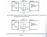
He also supported and preferred this "One End Only" topology and explained why, see first image below.
The Vcm source between the two chassis, indicate that although both chassis must be connected to mains gnd via their rep. mains cable, that because of induction to this mains gnd wire in the cable, the two chassis have potential differences between them. In the article measurements show this to be easily confirmed.
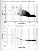
Example of comparing noise on a preamps power supply, with and without pin1 connected between preamp and main amp and both chassis connected to PE, is shown in the second image.
When you try this by simply lifting pin1 on the receiving side, but you still prefer SE, fair enough.
But rejecting balanced without having properly tried is, you name it.
Hans
Attachments
Understood. However, for Andrea's FIRDAC (which has more taps than yours), listening tests show best subjective SQ with 5/6MHz oscillators and two doublers. Could it be Andrea's clocks are highly symmetrical over time so that doubling as a practical matter tends to have less that the worst case effects? Maybe deeper notches from more taps can help? Could also be that other dynamic problems with data conversion may tend to mask any remaining effects of clock doubling? The point I am trying to get it at is there are things we may not fully know about in practice, yet we have some empirical evidence that what Andrea is doing with his dac seems to be working well.
I leave it up to everyone to decide for themselves to what extent they regard those listening tests as evidence, but as regards the technical side:
1. With 5.6448 MHz or 6.144 MHz clocks, there is no problem at all for DSD64 and DSD128, because the crystal frequency is no subharmonic of the sample rate.
2. For higher DSD rates, longer FIRDACs can indeed help to mitigate the issue further.
2b. The FIRDAC of this thread is a four-tap RTZ type, which is just long enough to get a notch at half the sample rate and reduce the effect of clock spurious at half the sample rate. It won't do much against spurs at a quarter of the sample rate, like you would get with DSD512 and a 5.6448 MHz crystal, but fortunately, there are normally no idle tones around a quarter of the sample rate, only lots of quantization noise.
3. It also depends on the type of digital sigma-delta modulator. For example, the PWM8 algorithm of my valve DAC should be far less sensitive to it than my chaotic algorithm, which should again be better than a single-bit modulator with no dither or chaos.
4. The clock subharmonic that Andrea reported on this forum before he got banned was much too large for a DAC without FIRDAC structure (or with a two-tap RTZ structure, like my valve DAC) and a simple modulator, see https://www.diyaudio.com/community/...jitter-crystal-oscillator.261651/post-6373471
5. I think it's a pity he got banned, but that is no technical remark.
Last edited:
Yes, don't have one in my hand right now but can probably dig it up. Phase noise is expected to increase as frequency goes up by using higher frequency crystals or by doublers. However, IIRC measurements showed Andrea's doublers produced a little less than the theoretical phase noise increase.Any phase noise plots for this cascaded setup? Thought multipliers degrade the clock quality
Hans,Not meant in any way to be a personal attack, but allow me to be amazed that all at the sudden balanced connections are getting a bad name. Balanced connections have many advantages, but have to be executed properly.
As I mentioned earlier, if not you will have two SE lines fighting each other, so in most cases not leading to an improvement over one single SE connection.
The Article that I published in Linear Audio was supported by Bill Whitlock, one of the authors of AES48, so not exactly someone.
He also supported and preferred this "One End Only" topology and explained why, see first image below.
The Vcm source between the two chassis, indicate that although both chassis must be connected to mains gnd via their rep. mains cable, that because of induction to this mains gnd wire in the cable, the two chassis have potential differences between them. In the article measurements show this to be easily confirmed.
Example of comparing noise on a preamps power supply, with and without pin1 connected between preamp and main amp and both chassis connected to PE, is shown in the second image.
When you try this by simply lifting pin1 on the receiving side, but you still prefer SE, fair enough.
But rejecting balanced without having properly tried is, you name it.
Hans
As I see it, Marcel’s DAC has this clever balanced action on his SE output configuration also. You saw me struggling to understand🙂 Typical textbook designs need another differential stage to sort things out for unbalanced outputs
So still in line with theory balanced is better. And as you indicated earlier Marcel’s design is more that meet the eye…
Last edited:
re-clock output?
//
Reclock the divided bit clock with a flip-flop running of a clean supply. That should help, if there is a high enough clock available to make it work.
I was planning to try re-clocking next. Clean MCK (22M/24M) out of oscillator is readily available. I2SoverUSB and Amanero have reclocking as I understand. So far I have not found the need for it but it seems this RTZ dac may well require one.
The FIFO is quite programmable. I could PM you the manual if you like. It can run on any output voltage levels from 3.3v LVCMOS up to 5v logic levels. Just depends on how its powered. In non-RTZ mode, and for your DSD dac, it would just output Native DSD: BCLK, and left and right DSD data. To implement RTZ it runs the BCLK at twice the normal DSD frequency and resets every other native DSD BCLK period DATA to a zero. Hence the analog output volume level drops as though Vref were set to half the voltage.
In principle you can remove R124, R127, R129, R131, R132 and R133 and connect the FIFO to the pads that drive the lines to the 74LV574As. The high level needs to be 5 V. The difficulty will be to connect it nicely, without large loops that couple with each other. Note that the bit clock will have to drive two clock traces that both get split near the 74LV574As.
The MUTE and DSDON inputs will not work normally. They still switch the mute relay, but won't block the data, like they normally do.
Last edited:
I was planning to try re-clocking next. Clean MCK (22M/24M) out of oscillator is readily available. I2SoverUSB and Amanero have reclocking as I understand. So far I have not found the need for it but it seems this RTZ dac may well require one.
Assuming an ordinary positive-edge-triggered flip-flop, you need 44 MHz to reclock 22 MHz. That is, 22 MHz clean clock should work up to DSD256, but not DSD512. You can make a clock doubler with an EXOR gate and a delay circuit, of course; the noise of the delay circuit only affects the falling edge, which doesn't trigger the flip-flop anyway.
Hans,
Regarding batteries, you make some very good points. However, there are also some downsides. Dacs need to run continuously for at least several days at a time. Batteries need to be recharged, and there would need to be several of them.
Also, I would not use SS nor power packs. Switchers can be a problem, and power packs may include SMPS regulation. The noise is measurable even though there is not a conductive path back to earth. There is radiated EMI/RFI produced, and switching noise can also be conducted along the ground path at, say, the power pack output. Its just more like a radio antenna than the usual ground loop noise source.
Also, batteries can have incredibly low rated/measured ESR, but no FR dependency is usually given. Therefore if someone really wants to go the ultimate route with batteries, probably linear regulation would be the safest bet.
Regarding transformers, there are some things I can't go into on that subject. However, there are commercial split-bobbin and or electromagnetically shielded transformers. There are also a few especially good power conditioners. The old PS Audio Regenerators were also very useful for isolation and clean power. IME it turns out those types things do matter too. What I use here are two dedicated, used Monster HTPS 7000 MkII conditioners, one for the bench and one for the stereo. Easy to hear they help, no DBT needed.
-Mark
Yes, you will need several batteries and yes they will have to be recharged every now and then.
But compared to a power conditioner they are very affordable. For less then $50,- you could have all the batteries you need, even cheaper then the Amanero board I had to buy for testing 😀
But when you want continuous clean power, you will need a different solution. That's where I use Virtual Batteries for my equipment.
I load a cap during 45msec from mains supply, completely disconnect the cap for 2.5 msec and then connect it to reload a second cap which is fully isolated from mains and is connected to a local power regulator giving clean power.
After 45msec I disconnect the first cap from the second one, leave it alone for 2.5msec and then reconnect it again to the mains supply for another 45msec to recharge it.
This 10Hz charging cycle is not peeping through in any way and it works already for at least 8 years without flaws.
Selecting for different caps and power regulator settings, I'm free to generate any voltage.
Hans

When the oscillator is 22/24MHz, and that's what BCLK needs to be, then a buffered copy of the oscillator can be used for BCLK. A copy can also be used reclock the data. When a lower BCLK frequency is needed then it can be reclocked too.
Yes, that should also work. You then need to multiplex between the master clock (DSD512) and the flip-flop that tries to reclock the bit clock (DSD256, 128, 64).
For low phase noise multiplexing, omron small signal relays can work pretty well. There is a shielded version rated for RF, if desired. Have also seen people use gate-able clock buffer chips to do clock switching.
Attachments
Last edited:
Yes, I can simply swap the on-board clocks to 45M/49M as I have those available as well. Or I use my external clock board that already has 45M/49M clocks. All clocks are low phase noise NZ2520SDAs.Assuming an ordinary positive-edge-triggered flip-flop, you need 44 MHz to reclock 22 MHz. That is, 22 MHz clean clock should work up to DSD256, but not DSD512.
@Hans Polak , funny, I did this with NP Black Gate caps 20 years ago, used IRF fet`s and a simple "knipperlichtschakeling", around 2 to 10 Hz. Lots of voltage loss with merely a few 1000uF`s, ended with a simple 7805 regulator.
The switching LF makes use of pretty oke insulation and the fact that the regulator`s performance is maximum at low frequencies.
Awesome to see someone else use it, I never knew they were out there;-)
The SQ is amazing, never any trace of nervousness, but never optimized it.
Sorry off topic
The switching LF makes use of pretty oke insulation and the fact that the regulator`s performance is maximum at low frequencies.
Awesome to see someone else use it, I never knew they were out there;-)
The SQ is amazing, never any trace of nervousness, but never optimized it.
Sorry off topic
I would like to thank Markw4 for the bravery to share his thoughts about the two DACs, he's been here for some time, he knows what he will have to go through. Looking from the side I think he is actually making a compliment to the RTZ DAC, we just hate "our" horse being a bit slower and finishing second in crazy race, don't we?
I would also like to thank everybody else for not shredding him to pieces with his "anti-enineering" questions, which would be easy, I guess we have fine gentlemen here. Wise readers and those who spent the time to educate themselves will separate the seeds, the crusaders will never put the swards to rest. Markw4 is a searcher and I respect that a lot, thank you, your words speak thousands to me.
Apologies for the OT.
It goes to show 2 people can see wildly different things, because I see none of those negatives you see, only the positives.
What I think you normally see and isn`t the case here, is because nobody feels their ego hurt if someone has a different perception about things. Let`s celebrate we`re not copies of one another, which is the only way progress is guaranteed.
What I think you normally see and isn`t the case here, is because nobody feels their ego hurt if someone has a different perception about things. Let`s celebrate we`re not copies of one another, which is the only way progress is guaranteed.
- Home
- Source & Line
- Digital Line Level
- Return-to-zero shift register FIRDAC