Do we have a scope of intended plan document? Or is the plan to find out the feasibility of a great DSD dac at an attractive price/performance ratio?...scope of the intended plan.
Please don't get me wrong. I am nitpicking small details. If I listen to your dac casually as it is configured now, it seems plausible that it could be about as good as it gets. Its only when directly compared with a better dac that one realizes there is more quality in the recording than was originally thought. Roughly how good is your dac as it is configured right now? I would say if Andrea's dac is an "A+" then your dac might be something like an "A-"If the purpose is to find out how well or how poorly my DAC works, it seems logical to let my DAC generate the RTZ and the doubled clock.
Still very good indeed, but probably not quite at its full potential. Maybe with a little more work it could be an "A" or an "A+"
Thing is there is no exact theory to predict exactly what it will take. We don't know exactly how it will respond to better clocking and better reclocking, for example, until we try it. Same for a more "tuned" Vref supply. Stability is one thing, tuning for perceptual SQ is another. Don't know how much it might help without trying it. And so on.
The FIFO is quite programmable. I could PM you the manual if you like. It can run on any output voltage levels from 3.3v LVCMOS up to 5v logic levels. Just depends on how its powered. In non-RTZ mode, and for your DSD dac, it would just output Native DSD: BCLK, and left and right DSD data. To implement RTZ it runs the BCLK at twice the normal DSD frequency and resets every other native DSD BCLK period DATA to a zero. Hence the analog output volume level drops as though Vref were set to half the voltage.I can't answer your question about how to hook up Andrea's FIFO buffer to my DAC, because I know nothing about Andrea's FIFO buffer. Is there a description somewhere about what output signals it produces in RTZ mode? What are the high and low levels?
Last edited:
Simple scope: to start with, how does Marcel’s DAC (in its original form) sound compared with other DACs that you have listened so far? Maybe simple improvements/mods later on and see…Do we have a scope of intended plan document? Or is the plan to find out the feasibility of a great DSD dac at an attractive price/performance ratio?
And then, there is something else: when Hans tested the previous solid state FirDAC, the report indicated narrow sound stage. Has this been sorted out with this new version?
I don't want to say until we have opinions from more listeners and or until we try better clocking. Right now its not so much that its clearly narrow so much as that its vague. At least it sounds that way to me. Better clocking will help tighten it up. Better Vref might help too. The problem with depth is likely the remaining low level masking/veiling. What's causing it I can't say for sure without starting to eliminate some possible causes. In medicine it would be called, diagnosis by exclusion. When do doctors use that method? When there is no diagnostic test that gives a more direct answer to the question....report indicated narrow sound stage...
If you want to know what the dac sounded like in what I called the "worst case" when I first hooked it up, it sounded like amateur diy. Go buy a Topping D90 and you will be better off. As always, most of the sound of a dac is due to the surrounding circuitry, not the actual D/A conversion part (e.g. the dac chip, if, say, it were an IC dac). There is nothing controversial about that. Most of the cost is also in the surrounding circuitry.
In terms of trying your clocks and Andrea's FIFO, that still fits into what would be considered surrounding circuitry.
Last edited:
Assuming they are listening on a system good enough to discern the performance of the DUT. Also assuming they have a reference standard (e.g. Andrea's dac, or whatever you want to ship out to their listening session site) to show what is really on the recording. Without thinking about issues like that you can have people listening on poor/problematic systems (even if the owner thinks its the greatest thing ever), and you will get bad data in return....with listening tests, the impressions of the majority need to be taken in account…
")
I have a Benchmark amp too. For my speakers, mostly replaced it with an ah-hem... 're-capped' Aragon 8008 MkII (a little more than re-capped). Now moved on to Marantz MA9S2 Mono Blocks. Aragon and Benchmark not in use at the moment, might be persuaded to part with one or the other.
When I used to use the Benchmark I just used an adapter to SE input. IMHO there were some quirks to that amp that didn't show up in standard measurements. IIRC there is a trick to produce measurements of quirks in some such situations.
When I used to use the Benchmark I just used an adapter to SE input. IMHO there were some quirks to that amp that didn't show up in standard measurements. IIRC there is a trick to produce measurements of quirks in some such situations.
It's best to look at mods for a dac from a compartment based perspective.
Like you mentioned the surroundings.
So that means you have all situated around the core, which is the dac itself, that what generates the signal, the energy packets. That is the core.
All other circuitry is supportive. There are like ring structures around it.
The local power supply and the rtz circuit here is the first ring, the second ring is the power supply e.g. from wall power to first regulated DC, the base signals needed like Clock and Data input (Amanero but imho 2 steps better: a BeagleBone) (and its local power supply, which is usually 1 integrated thing), as well as cabling/wires needed to glue these things together.
You modify from the outer ring and see/listen what each do regarding SQ, order is yours to choose, based on what you seem lowest fruit and must haves and on what you have to replace it with.
You work to the inside, 2nd ring but hardly ever touch the core unless you find issues with it and absolutely know what you're doing.
Something like that.
Edit: output structures can be like, or are mostly used in a mix of technical must haves (filtering and amplification), but many times serves as a means of commercial seasoning. Buzzword like tube, passive filtering, solid state vs IC are used to sell a product. Usually I leave them alone for that reason, as it is what sold the product sometimes even more than how cool it looks or what resolution it has.
Marcel should actually be the one to answer these questions, but I don't see him having in mind commercial inspiration and sees these product purely as a nice means to some mental gymnastics and a nice addition to the DIY community, but I might be mistaken?
Last edited:
The FIFO is quite programmable. I could PM you the manual if you like. It can run on any output voltage levels from 3.3v LVCMOS up to 5v logic levels. Just depends on how its powered. In non-RTZ mode, and for your DSD dac, it would just output Native DSD: BCLK, and left and right DSD data. To implement RTZ it runs the BCLK at twice the normal DSD frequency and resets every other native DSD BCLK period DATA to a zero. Hence the analog output volume level drops as though Vref were set to half the voltage.
Are there inverted outputs available? For each channel, my DAC requires data and inverted data, both with zeros inserted to make it RTZ. That is,
Positive data: D0 0 D1 0 D2 0...
Negative data: DN0 0 DN1 0 DN2 0...
where Dn are the data bits and DNn are their inverted values.
In each cycle, either Dn or DNn is 1, so you get the same, data-independent, load on the reference, as long as the positive and negative sides of the DAC match.
This got me thinking. It would be fairly straightforward to do all that in MCU. So instead of generating DCLK, DL and DR as it now does MCU would generate doubled DCLK, RTZ DL+DLN and RTZ DR+DRN. Not much processing in SW. I need to try that later. It would however require STM32H7 instead of STM32F7 since the latter has some limitations in clock generation.
DSD signals are generated already now with MCU SAI (serial audio interface) from on-board or external clock. Do you see any far-off phase noise or clock spuries in my ES9038Q2M measurements?
Actually I should be able to do a proof-of-concept on one channel with my existing STM32F7 board. I'll just use DR for DLN. So MCU would output doubled DCLK and RTZ DL+DLN straight to 74LV574s.
Actually I should be able to do a proof-of-concept on one channel with my existing STM32F7 board. I'll just use DR for DLN. So MCU would output doubled DCLK and RTZ DL+DLN straight to 74LV574s.
Last edited:
No, because as far as I can see, you didn't measure the clock spectrum.
It could very well be that the ES9038 is less sensitive to far-off phase noise and spurs than my DAC. That depends on the internal structure of the ES9038 (I don't have time to read its datasheet at the moment).
It could very well be that the ES9038 is less sensitive to far-off phase noise and spurs than my DAC. That depends on the internal structure of the ES9038 (I don't have time to read its datasheet at the moment).
re-clock output?I wonder how clean you can get the clock that way. Far-off phase noise and clock spurious can mix out-of-band quantization noise into the audio band.
//
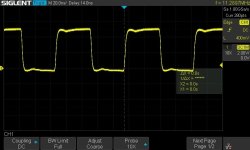
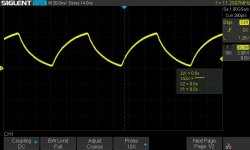
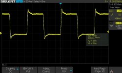
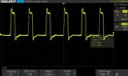
Here are the signals to/from U28 in my board. DCLK signal in this case comes directly from a 11.2896MHz clock so MCU can be ruled out. I used a probe with spring clip for ground. Clock doubler (U28 pin 7) looks very jittery. In this case it is not connected to anything so there should be no reflections. I have already swapped U28 but signals look still the same.I haven't a clue what the input signals of U28 look like, but Hans did have a look at the output of U28A on my prototype board, using a 470 ohm resistor, 50 ohm coax cable and 50 ohm termination at the input of his oscilloscope. It looked quite nice, actually, with a pulse width of about 8 ns, closer to the design target than I had expected.
Attachments
I agree to to start from the outside, which to my opinion should be to use impeccable power supply by means of batteries.It's best to look at mods for a dac from a compartment based perspective.
Like you mentioned the surroundings.
So that means you have all situated around the core, which is the dac itself, that what generates the signal, the energy packets. That is the core.
All other circuitry is supportive. There are like ring structures around it.
The local power supply and the rtz circuit here is the first ring, the second ring is the power supply e.g. from wall power to first regulated DC, the base signals needed like Clock and Data input (Amanero but imho 2 steps better: a BeagleBone) (and its local power supply, which is usually 1 integrated thing), as well as cabling/wires needed to glue these things together.
You modify from the outer ring and see/listen what each do regarding SQ, order is yours to choose, based on what you seem lowest fruit and must haves and on what you have to replace it with.
You work to the inside, 2nd ring but hardly ever touch the core unless you find issues with it and absolutely know what you're doing.
Something like that.
Edit: output structures can be like, or are mostly used in a mix of technical must haves (filtering and amplification), but many times serves as a means of commercial seasoning. Buzzword like tube, passive filtering, solid state vs IC are used to sell a product. Usually I leave them alone for that reason, as it is what sold the product sometimes even more than how cool it looks or what resolution it has.
Marcel should actually be the one to answer these questions, but I don't see him having in mind commercial inspiration and sees these product purely as a nice means to some mental gymnastics and a nice addition to the DIY community, but I might be mistaken?
No matter how good a power supply is, there is always a capacitive coupling to mains and feedthrough of unwanted "noise".
One example is the improved performance with a separate 5 Volt on the Amanero instead of the USB supply.
Although the USB supply measured perfectly suited for the job, see #860, but as already Mark mentioned, my own experience is also that a separate supply instead of USB supply improves sound, although it can't be measured.
A battery powered supply is even one step further, it makes little sense to ask why, just follow your ears.
When having replaced all mains supplies by batteries, one can go back step by step by replacing battery by battery by main supply and listen to the effect, when no difference, voila the mains supply can be kept at that point.
It's a relatively simple test without having to change anything to the Dac.
And be aware that Marcel has put a lot more know how in the design than meets the eye, it's not just a series of components tied together, it will be very hard to improve the digital design.
There is just one little aspect that I would have preferred, a separate supply for the filter board instead of one +/-15Volt for both PCB's, for the same reason as giving the Amanero it's own supply, but this is also very easy to achieve with two low cost +/-12Volt lead acid batteries without any modification to the circuitry and the Dac board could be powered from Jan's Silent Switcher fed by a 5V powerbank.
With having everything powered by separate batteries, you have IMO the best possible starting point for further experimenting.
I'm almost sure you will at that point listen to a different Dac.
Just my two cents,
Hans
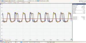
Here are my measurements at U28 pin 7 at DSD512.Here are the signals to/from U28 in my board. DCLK signal in this case comes directly from a 11.2896MHz clock so MCU can be ruled out. I used a probe with spring clip for ground. Clock doubler (U28 pin 7) looks very jittery. In this case it is not connected to anything so there should be no reflections. I have already swapped U28 but signals look still the same.
I use the persistence mode on my scope to better detect any jitter, the horizontal red line shows the trigger level.
The clock doubler produces an asymmetric pattern of a shorter period S and a longer period L, where L+S is the period of the incoming clock, because of assymetric triggereing of U28.
So what seems to be jitter, are the L and S periods in between, but Marcel explained that this has no effect on the Dac.
If any jitter exists, it must come from the Amanero.
Hans
Attachments
Yes, it can do exactly that.Are there inverted outputs available? For each channel, my DAC requires data and inverted data, both with zeros inserted to make it RTZ. That is,
Positive data: D0 0 D1 0 D2 0...
Negative data: DN0 0 DN1 0 DN2 0...
where Dn are the data bits and DNn are their inverted values.
In each cycle, either Dn or DNn is 1, so you get the same, data-independent, load on the reference, as long as the positive and negative sides of the DAC match.
- Home
- Source & Line
- Digital Line Level
- Return-to-zero shift register FIRDAC