If you`re interested, there is supposedly a way to check if it`s a hardware pin issue by making use of the "DSDSWAPPED" version.

Why not just get it up and running and form an initial impession?EDIT: Waiting to hear back from Acko if its okay to solder on his nice new boards...
There is no output connector soldered onto the board. Use clip leads on the relay outputs somehow?
There is was already an input pin header soldered to the dac board, and also already a pin header soldered to the Amanero. Which one did you want me to unsolder and replace with a socket?It's a pity you need a ribbon cable, but I'm glad to read that it is very short.
Hi Mark, please go ahead with any soldering work as necessary. Looking forward to your listening impressions🙂
This whole Amanero issue of 1 channel glitching is something that has been plagueing one of the 3 boards I had as well. Exactly same issue: only with DSD512 and only 1 channel. I didn`t measure it, because the other boards did not have a problem at all, not with the same pc and cable, nor with different ones.
The boards were bought with time in between, so it could be just a certain batch suffering from it. I bought the boards at least 5 to about 8 years ago.
I don`t remember ever fixing it, but I did try reflashing it, different firmwares etc etc.
So it is an Amanero issue that occurs on some of the boards, but only when there is a lot of digital activity and with normal (sort of "random") data, not with short repetitive patterns. Wild guess: some issue with the digital power decoupling and/or wiring after the on-board 1.8 V and 3.3 V regulators. Maybe there is a (broad) resonance somewhere that gets excited by random data and not by short repetitive patterns.
Was there any difference in board revision code between the Amanero boards that work fine and the one that doesn't?
There is was already an input pin header soldered to the dac board, and also already a pin header soldered to the Amanero. Which one did you want me to unsolder and replace with a socket?
As far as possible, the DAC has everything data-related on the bottom side and everything clock- or reference-related on the top side, so the inner layers act as shields between these parts. As there is a lot of data handling going on on the Amanero board, I think it would have to be mounted below the DAC board to fit best with the data on the bottom, clock and reference on the top strategy, but then again, there is hardly any overlap between the Amanero and DAC boards, so the DAC board inner layers can't shield much anyway.
@nautibuoy and @Hans Polak , how did you mount the Amanero with respect to the DAC?

@Hans Polak If you are still interested: a USB2.0 interface in high-speed mode (that is, not signalling slowly for compatibility with earlier types of USB) uses a 90 ohm balanced line that is terminated on both sides with two 45 ohm +/- 10 % resistors to ground. For each symbol, the transmitting USB port sources a current of nominally 17.78 mA into one of the two lines of the balanced pair. This results in a common-mode level of 200 mV and a differential voltage that switches between -400 mV and +400 mV. You can find all about it in chapter 7 of usb_20.pdf in the .zip file you can download from https://www.usb.org/document-library/usb-20-specification
One of the nice things about using short, maybe 2" or less, ribbon cable is that you can move the USB board around a little with respect to the dac board and see if the sound changes at all. IME sometimes it can. IMHO radiated noise coupling is what the relative movement versus sound tends to suggest, at least in cases where an effect is seen.
I don't own an Amanero, I've used the RTZ DAC with two different inputs, first was via a JLSounds i2soverUSB V2 (using a small adaptor PCB) that I used with HQPlayer, and the second was Pavel's DSD'it (on a Beaglebone) that was used with Roon. Both inputs used female headers to plug onto the male header on the underside of the RTZ DAC.@nautibuoy and @Hans Polak , how did you mount the Amanero with respect to the DAC?
Incidentally, my JLSounds adaptor board is able to illuminate LEDs to show the incoming DSD rate (44.1 DSD64, 48 DSD64, etc.)


Last edited:
One of the nice things about using short, maybe 2" or less, ribbon cable is that you can move the USB board around a little with respect to the dac board and see if the sound changes at all. IME sometimes it can. IMHO radiated noise coupling is what the relative movement versus sound tends to suggest, at least in cases where an effect is seen.
You can do whatever experiment you consider useful, of course.
The reason I'm worried about the effect of the ribbon cable is that the ribbon cable I used to connect the digital part of my earlier solid-state DAC to the inputs of the prototype RTZ shift register DAC much increased the noise floor. The cable was several times longer than 5.08 cm, but it had grounds between the data and clock that you won't have with the Amanero pin-out (at least not when you connect the ribbon cable the way they are usually connected, with the first wire to the first socket of one row of the connector, next wire to the first socket of the other row, third wire to the second socket of the first row, fourth to the second socket of the second row and so on).
I really had to split the ribbon cable to keep the bit clock far away from the data. In the end, I switched to using thin coax for the bit clock.
Hi Marcel,
Reason for starting with Amanero is because the dac board is designed to that interface standard. Obviously, its not completely ideal. However, each of the I2S lines has a ground on the adjacent pin the next row of the pin header.

So Amanero pin 13 ribbon wire should be between the wires for pins 3,4 in the ribbon cable, etc. At least that's why it seems to me.
That said, I can check for noise on the lines at the dac board with an active low capacitance scope probe. If a problem, an easy fix might be to change the zero ohm I2S input resistors on the dac board to as much as 50R. Slows rise time a little, but often works quite well depending on the particular dac. Otherwise I can unsolder a pin header and replace it with a socket on one of the devices. We'll see.
Later, when I get around to trying with I2SoverUSB, I also have an interface board that is designed for use with the FPGA-based Simple DSD Converter (which also uses Amanero pinout). The adapter can probably be used to interface between I2SoverUSB and the dac board instead.
Reason for starting with Amanero is because the dac board is designed to that interface standard. Obviously, its not completely ideal. However, each of the I2S lines has a ground on the adjacent pin the next row of the pin header.
So Amanero pin 13 ribbon wire should be between the wires for pins 3,4 in the ribbon cable, etc. At least that's why it seems to me.
That said, I can check for noise on the lines at the dac board with an active low capacitance scope probe. If a problem, an easy fix might be to change the zero ohm I2S input resistors on the dac board to as much as 50R. Slows rise time a little, but often works quite well depending on the particular dac. Otherwise I can unsolder a pin header and replace it with a socket on one of the devices. We'll see.
Later, when I get around to trying with I2SoverUSB, I also have an interface board that is designed for use with the FPGA-based Simple DSD Converter (which also uses Amanero pinout). The adapter can probably be used to interface between I2SoverUSB and the dac board instead.
Last edited:
Marcel,@Hans Polak If you are still interested: a USB2.0 interface in high-speed mode (that is, not signalling slowly for compatibility with earlier types of USB) uses a 90 ohm balanced line that is terminated on both sides with two 45 ohm +/- 10 % resistors to ground. For each symbol, the transmitting USB port sources a current of nominally 17.78 mA into one of the two lines of the balanced pair. This results in a common-mode level of 200 mV and a differential voltage that switches between -400 mV and +400 mV. You can find all about it in chapter 7 of usb_20.pdf in the .zip file you can download from https://www.usb.org/document-library/usb-20-specification
Thx for your info´s regarding USB2.0
I took a look at the huge amount of documents, especially chapter 7 of USB_20.pdf , but could easily spend several days in reading them all.
But since Marco reported the same problem with the Amanero, the need to go in much depth has largely been diminished,
However, I connected my scope to the USB D+ and D- signals referred to ground at the point where they entered the Amanero, and found that this board must obviously be using a current input, since the differential Voltage on the lines did not exceed a few mV in receiving mode.
Nevertheless, the Amanero was still working with DSD-On high while outputting the correct clock and data signals.
When transmitting back over USB to the computer , I could see short 400mV packets at a low repetition rate.
That´s where my search ended, this USB thing is a world of its own.
Hans
Its up and running, playing through a Neurochrome HP-2 and pair of Audeze LCD-X. Playing back SACD rips through PlayPcmWin and WASAPI Exclusive Mode, for now at least. Will let it warm up for awhile before describing any initial impressions. Probably should run at least 24h to be fair. Maybe even for a few days.
Marcel, I don`t know of any revision differences between them, as I wasn`t going to return them and I didn`t want to spend more time on the issue. I opt to toss away faulty electronics if the price is not too high;-)
But, the previous image of Hans looks strange to me, all 3 looked way more like this one here:
https://www.audiophonics.fr/en/inte...l-interface-usb-384khz-to-i2s-dsd-p-7403.html
But, the previous image of Hans looks strange to me, all 3 looked way more like this one here:
https://www.audiophonics.fr/en/inte...l-interface-usb-384khz-to-i2s-dsd-p-7403.html
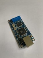
The pic Hans posted kind of does look a little odd, although maybe its just the color. A pic of the bottom side might be helpful.
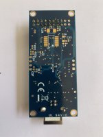
Looks most likely real to me, although mine don't have pads for additional components on the bottom. Could be a model made for OEM use. Something like that.
Clones I've seen didn't have the CE marking, and the bottom plastic part of the USB connector was black instead of white. Another difference may be that real Amaneros have a ferrite bead for L1, whereas clones I have seen use a resistor.
Clones I've seen didn't have the CE marking, and the bottom plastic part of the USB connector was black instead of white. Another difference may be that real Amaneros have a ferrite bead for L1, whereas clones I have seen use a resistor.
Could this be a more recent model ?
Compared to the picture that Marco sent, mine has also receive and transmit connection points at the edge for SP/DIF communication.
Hans
Compared to the picture that Marco sent, mine has also receive and transmit connection points at the edge for SP/DIF communication.
Hans
- Home
- Source & Line
- Digital Line Level
- Return-to-zero shift register FIRDAC