Hi Marcel,So all in all, you have an interface board with an ASIO driver that is supposed to have two methods to handle DSD bitstreams, the default ASIO native DSD method and the DoP method. The default method doesn't work at all and the DoP method randomly produces incorrect data at DSD512. 😲
I tested again all possible options, but the only combination that works is as mentioned before: Amanero Asio driver plus JRiver set to DSD bitstreaming, meaning DoP.
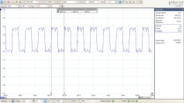
When playing without DoP, all 4 bitrates from DSD64 to DSD512 produce nonsense output, while keeping DSD-On low.
With DoP, DSD-On goes high for all 4 bitrates and the output conforms to what's offered by JRiver.
Without having the Firdac board, it's not possible to see glitches in the signal, but I measured Left, Right and Clock with 450R in series with a 50R Coax, terminated with 50R at the scope input.
I was surprised to see how well the signals were looking with this termination, so maybe the 100K on the Firdac board could be lowered quite a bit, possibly giving better results?
As an example see the 22.579 Mhz clock at the Amanero's output terminated as described for DSD512.
The left and right channel output signals had identical risetimes and shapes.
Recordings were taken at 2nsec sample intervals. For an even better signal shape I could have used 1nsec intervals, which I forgot to use, but this is probably good enough to show what a low termination does to the signal.
Hans
Attachments
The Amanero has series termination resistors at its outputs, see https://amanero.com/CPLD_E.pdf If I were to include parallel termination resistors on the DAC board, the voltage division between the termination resistors would attenuate the high level such that it would no longer be TTL compatible. The DAC might not work at all then.
If the series termination resistors do what they are supposed to, the waveforms should still look pretty good with the coax connected directly to the Amanero, without 450 ohm and without 50 ohm termination at the scope input. That's assuming the CPLD has an output impedance much smaller than the 47 ohm of the series resistors.
Regarding your remark "Without having the Firdac board, it's not possible to see glitches in the signal", you did see strings of 16 ones before. How did you get your scope to trigger on them then? By triggering on the DAC output? When you connect a makeshift low-pass filter with a time constant of 1 us or so to the data output with the glitches, you should see glitches at the low-pass output if they are still there.
Hi Marcel,
The signal directly from the Amanero is still very noisy when using a 100Khz filter making it difficult to see any glitches.
But the question is, what would be the purpose of investing more time as already done.
Driving Amanero from JRiver in DSD bitstream was again confirmed to be correct, so DoP is the only mode that Amanero accepts for all DSD bitrates.
One channels performed correct and the other channel produced glitches but only for DSD512.
On the Firdac board I experimented with 4.5Volt to 5.5Volt supply with no change and all other measurements confirmed the Firdac’s correct functioning
So, when this very Amanero board has a problem in one channel using DSD512, so be it and doesn’t automatically say all Amaneros have.
Using the one channel, that performed without any flaws, was IMO adequate to produce valid test results for the combination Amanero / Shiftregister Firdac.
Hans
I was just wondering if your remark meant that the spikes only occur when the Amanero and DAC are connected, which would be very peculiar, or simply that you have difficulty measuring them without DAC due to a lack of a suitable signal to trigger your oscilloscope.
Think I have an Amanero around here somewhere. Acko's Marcel's RTZ dac is predicted to arrive hereabouts on Tuesday. Maybe I can take a look at it with Amanero at some point.
It was just the difficulty of finding a trigger point for a small spike in this noisy signal.I was just wondering if your remark meant that the spikes only occur when the Amanero and DAC are connected, which would be very peculiar, or simply that you have difficulty measuring them without DAC due to a lack of a suitable signal to trigger your oscilloscope.
I don’t think that the Amero can even “see” that the DAC is connected, so spikes have nothing to do with the DAC, I thought to have mentioned that.
Hans

At the time you are ready to take a look, I could send you the .dsf files with silence that I was using.Think I have an Amanero around here somewhere. Acko's Marcel's RTZ dac is predicted to arrive hereabouts on Tuesday. Maybe I can take a look at it with Amanero at some point.
Then we have a 1:1 comparable situation.
Hans
Dac boards arrived this afternoon. Will start looking at how to hook them up in the morning 🙂
The RTZ boards have had a long trip, probably around two thirds of the way around the Earth - hopefully they've not suffered any damage?
Last edited:
By the way, see post #762, https://www.diyaudio.com/community/threads/return-to-zero-shift-register-firdac.379406/post-7403044 , for the .dsf files with repetitive silent patterns and post #763 for a Pascal program that generates a non-repetitive silent DSD512 .dsf file as was used to compare the measurements of Hans and me. With small modifications, the Pascal program can also generate tones.
For some reason, the problem did not occur with the repetitive silent patterns, but it did with silence generated by JRiver and with non-repetitive silence generated by my Pascal program.
For some reason, the problem did not occur with the repetitive silent patterns, but it did with silence generated by JRiver and with non-repetitive silence generated by my Pascal program.
Last edited:
In LTspice I replicated the spike pattern recorded from the one Amanero channel that was giving these anomalies at DSD512, to get some feeling what spectral content this could possibly cause.
See first image for a 20msec recording from a silent track with unwanted spikes.
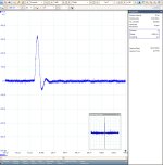
Second image is a magnified spike, showing a ca 5usec spike, of almost triangle waveform.
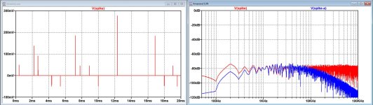
That is wat I replicated in LTspice, see third image.
This third image is also showing the spectral content Unweighted in red and A-Weighted in blue.
I may be completely wrong, but looking at the spectrum I have my doubts whether the effect of these spikes can be noticed while listening at normal audio levels.
In this case measuring is revealing a nasty problem that should not be there in the first place, but I still wonder whether this is a systematic or an exemplary problem that was not discovered before.
So, I'm looking forward to see Mark's discoveries.
Hans
See first image for a 20msec recording from a silent track with unwanted spikes.
Second image is a magnified spike, showing a ca 5usec spike, of almost triangle waveform.
That is wat I replicated in LTspice, see third image.
This third image is also showing the spectral content Unweighted in red and A-Weighted in blue.
I may be completely wrong, but looking at the spectrum I have my doubts whether the effect of these spikes can be noticed while listening at normal audio levels.
In this case measuring is revealing a nasty problem that should not be there in the first place, but I still wonder whether this is a systematic or an exemplary problem that was not discovered before.
So, I'm looking forward to see Mark's discoveries.
Hans
Attachments

Last edited:
You simulate white noise of about -80 dBV per 50 Hz bin, roughly -56 dBV A-weighted, with a very peculiar probability distribution. Why would that be inaudible?
Because of the spiky nature, I would expect it to sound like minor click noise or like a slightly dirty vinyl record. Anyway, we will see.
Because of the spiky nature, I would expect it to sound like minor click noise or like a slightly dirty vinyl record. Anyway, we will see.
Last edited:
Hi Marcel,
Yes -56dB(A) is correct.
My experience is that at “normal” listening levels this -56dBA is about the point where you start hearing the noise in silence.
When playing music it will be masked.
It’s a pitty I did not audition the DSD512.
It was just a challenging exercise to get some feeling about the magnitude.
But, to be absolutely clear, this anomaly is highly unwanted and should not at all be there.
Hans
Boards arrived in good condition. Thinking about what to do first. Probably set it up with an Amanero running on USB power. Just to see how it might sound in typical use.
Also, at some point if I need/want to probe it, I may need Acko's permission to solder on some test points and or scope ground clip locations. We'll see.
Also, at some point if I need/want to probe it, I may need Acko's permission to solder on some test points and or scope ground clip locations. We'll see.
Marcel,
Have you any idea how to measure the signal that's transferred over a USB connection.
I suppose info transfer is through current exchange, making it more difficult to catch, unless a very high speed current sensor will be used.
Suppose there are spikes in this signal caused by the computer, that could eventually disturb the Amanero.
Hans
It goes through a characteristically terminated differential transmission line as far as I remember, but I'll look it up in the USB2.0 spec. The spec is easy to find on the internet, finding something in the huge spec document is a different matter.
Long time lurker here, great thread, and I can`t wait to read Mark`s description of it`s SQ, the more so while taking the upgrade path for the interface and hear what these bring the DAC.
I have high hopes, given Nautibuoy`s early test results and my own and others`experience with similar dacs, that these respond very well to mods Mark suggest.
This whole Amanero issue of 1 channel glitching is something that has been plagueing one of the 3 boards I had as well. Exactly same issue: only with DSD512 and only 1 channel. I didn`t measure it, because the other boards did not have a problem at all, not with the same pc and cable, nor with different ones.
The boards were bought with time in between, so it could be just a certain batch suffering from it. I bought the boards at least 5 to about 8 years ago.
I don`t remember ever fixing it, but I did try reflashing it, different firmwares etc etc.
Did you measure the same glitches at that hardware pin at the same speeds (352,8KHz PCM)?
Did you compare the settings with a board that is without this defect?
There have been many different firmwares available for this board, one more or less optimized for DSD or other I2S formats as well as bug fixes. Sorry for not searching this thread, but just to be sure, the link to the various firmware versions:
http://www.amanero.com/combo384_firmware.htm
At the bottom, there is also the link for the Windows drivers.
Sorry if this has been asked or tried before, I think it needs consideration before usb signals will get examined.
Point I wanted to make, is that it never was an issue with the connected pc or cable used, it really was the board itself and it had this problem from the start.
The only thing I didn`t check is if the output pin of the CPLD suffered from a mild ESD issue. The board was in excellent cosmetic condition, psu was stable and the resistors were within spec.
Marco
Just re-flashed two Amanero boards here. They had been configured for external master clocks. Now back to standard.
Amanero website says:
"The boards by default are programmed with CPLD_for_1080 and firmware DSD512x48x44"
Also says:
"it requires to download the main drivers"
Also made a very short ribbon cable to connect Amanero to Marcel's dac.
EDIT: Waiting to hear back from Acko if its okay to solder on his nice new boards...
Last edited:
- Home
- Source & Line
- Digital Line Level
- Return-to-zero shift register FIRDAC