Bohrok,
Have you any idea how many blocks with silence in a .dsf file are being sent before the signal starts
Hans
Have you any idea how many blocks with silence in a .dsf file are being sent before the signal starts
Hans
I have a couple of, probably dumb, questions to the design of the FIR dac portion of this construction:
Is the reason to make the shift registers out of 74 FF because they are faster than traditional shift registers ( as f.ex. 74ahct595)?
What is the reason for the pretty low numbers of tabs compared to something like the DSC1 and DSC 2?
Is the 74xxx574 kind of shift register FIR DAC usable in a non RTZ construction , with just a 7474 FF to make the DSD data n and DSD data p signals?
Why the need of a double speed DSD clk?
I am not very fond of clk doubler circuits so if a DSD x2 clk is needed, wouldn't it be better to compare the MCK with the DSD clock and let that control a divider for the MCK to make the DSD x2 clk?
Thanks in advance
This probably depends on many things such as the player, DSD rate, format (DoP/native DSD). E.g. foobar2000 sends about 14000 4-byte zero value samples at DoP64, at DoP128 twice as many and at DoP256 4 times as many. These are sent before first actual samples with DoP markers. I haven't checked if foobar2000 sends DSD silence after those zero value samples.Have you any idea how many blocks with silence in a .dsf file are being sent before the signal starts
EDIT: seems that at DoP128 and DoP256 foobar2000 does not send any additional silence bytes after those zero valued samples.
Last edited:
Is the reason to make the shift registers out of 74 FF because they are faster than traditional shift registers ( as f.ex. 74ahct595)?
Ask Marcel, but probably not.
With enough additional logic I think 595 with split supplies (like Pavel's latest) is preferable, as we have a set of serial and a separate set of parallel latches.
Each time the chain of gates that makes up each latch in a x74 circuit updates the internal states we get a lot of switching noise on the supplies.
In a 595 we can adjust timing (this is not done in DSC NRZ DAC's sadly) we could do the transfer of the states on the serial registers to the output registers just before the next clock updates the serial latches. That means all the switching noise, ringing in the leadframe etc. is over, by the time we trigger the update to the output latches.
Even better would be Logic that can (say) use 2.5V or even 1.8V on the input (serial latches) side and 5V on the output side and has a suitable pinout with Vcc and Vss (GND) pin's next to each other, not at opposite ends of a long package.
What is the reason for the pretty low numbers of tabs compared to something like the DSC1 and DSC 2?
Again, this is to Marcel, for his personal reasons.
But I prefer fewer taps, with non-uniform weighting.
If we take Jussi's original DSC, at DSD (64), the impulse response of the 32 Tap FIR completes in the same time as one sample of 88.2kHz PCM. If we instead consider a non-uniform weight 8-Tap, with a similar rejection of noise as Jussi's 32 Tap, the impulse response in the same time as a 705.6kHz PCM sample.
In listening I have preferred non-uniform weighting 8-Tap designs to DSC with 32 Equal taps each time. This took the form of both the Electart DSD-Principle design which is roughly the same as a discrete DSD1700 from BB/TI with an FPGA for a lot of the functionality as well as the variety of BB/TI Chip's.
Is the 74xxx574 kind of shift register FIR DAC usable in a non RTZ construction , with just a 7474 FF to make the DSD data n and DSD data p signals?
In theory - YES. In practice this creates a massive nightmare in the clock tree to feed that many IC's a clock at EXACTLY THE SAME TIME and it seems that currently available logic switch Q and Qn at the same time. Pavel did a DSC2 this way and failed to make it work well enough.
I suspect if you do each bit with a double differential 74XX74 using both halves with one half inverted all these issues come out in the wash but we are up even more on clock pin Count and an even bigger clock tree nightmare.
Here is my own solution for a "clock tree" to drive 8 + 1 MCK at 1024FS for 8 separate DAC IC's (8 clock pin's) and one "other systems" such as FPGA's etc. The clock driver was a massive parallel set of unbuffered inverters with each line back terminated at 50 Ohm.
Why the need of a double speed DSD clk?
RTZ means for half (or less) of the time of one bit clock the output is returned to zero. This implies a clock that is phase locked to bit clock and offers low jitter.
What is more, if we use sufficiently fast logic, we could make RTZ with not 50% Duty Cycle, but 75% duty cycle, needing a 4 X BCK clock.
We can extent the principle again using and 8 X BCK system clock allows us 87.5% Duty Cycle, which means many of the drawbacks of the RTZ FIR DAC are reduced from 50% to 12.5%.
I am not very fond of clk doubler circuits so if a DSD x2 clk is needed, wouldn't it be better to compare the MCK with the DSD clock and let that control a divider for the MCK to make the DSD x2 clk?
Why not make a sufficiently fast MCK to start with?
If we operate at DSD256 (11.2896/12.288) a 45.1584/49.152MHz MCK allows for 75% RTZ and logic that is highly capable at 50MHz in not that hard to find. Then drive all the required logic from that.
I believe Marcel used the clock doubler to separate the DAC section and the source, needing only BCK and Data. I am sure that if Marcel HAD included a clock, no matter which one it was, it would have been the "wrong clock" for most.
Thor
Is the reason to make the shift registers out of 74 FF because they are faster than traditional shift registers ( as f.ex. 74ahct595)?
The shift registers are made out of 74LV574A's. The 74LV family is faster than 74AHC(T) and has a smaller difference between the high and low output resistances, if I remember well.
What is the reason for the pretty low numbers of tabs compared to something like the DSC1 and DSC 2?
I just took the smallest number of taps needed to suppress idle tones around fs/2. As the shift register runs at 2fs, that boils down to four taps.
Besides, I wanted to make the current waveform drawn out of the reference supply as data-independent as possible, and I wanted it to consist only of harmonics of the bit clock. Ripple on the reference supply at exact multiples of the bit clock frequency does no harm, because it can only mix down images of the low-frequency spectrum.
To achieve that, for each channel, I have a positive and a negative DAC. In each clock cycle, either the positive tap or the corresponding negative tap draws current from the reference. As long as they match, their summed current is data-independent.
To get good matching, I interdigitated flip-flops from the same 74LV574A chip. That is, half the flip-flops in the 74LV574A are part of the positive DAC and the other half of the negative DAC. This may leave a systematic difference due to different on-chip wire lengths to the supply and ground bond pads, so I took a second 74LV574A that has the positive and negative DACs swapped.
All in all, I need 16 flip-flops for a four-tap FIRDAC. A longer shift register would reduce the sensitivity to the phase noise floor, but would also make the circuit more complicated.
Is the 74xxx574 kind of shift register FIR DAC usable in a non RTZ construction , with just a 7474 FF to make the DSD data n and DSD data p signals?
I guess so. Of course you will lose all the advantages (and disadvantages) of RTZ.
Why the need of a double speed DSD clk?
By definition, the RTZ logic inserts zeros between each pair of data bits. Hence, the bit rate doubles, and hence, I need a doubled clock.
I am not very fond of clk doubler circuits so if a DSD x2 clk is needed, wouldn't it be better to compare the MCK with the DSD clock and let that control a divider for the MCK to make the DSD x2 clk?
You could do that, but you need to have an MCK then and it needs to be high enough in frequency.

@ThorstenL : ... just happened to see your post above - interesting thoughts you present here. One additional question if I may: What constitutes the difference between "uniform weighting" and "non-uniform weighting"? Any chance you would happen to have a link to a "layman-like" text that describes this, or something similar? Googling the topic essentially gave no result ...
Cheers, Jesper
Cheers, Jesper
... just happened to see your post above - interesting thoughts you present here. One additional question if I may: What constitutes the difference between "uniform weighting" and "non-uniform weighting"?
Essentially, a FIR DAC/Filter etc. is a delay line with taps along the line and summing signals from each tap. This creates pre- and post-echo and a given filter response in the frequency domain (time domain and frequency domain are just different ways of looking at the same thing).
Old "bucket brigade" reverb (originals are legendary and sought after among guitarists) are literally analog FIR filters.
Old analogue colour TV's used such delay lines implemented in mechanical hardware (piezoelectric/glass) to decode the colour encoding.
Actually with hindsight I am looking at the whole tech underpinning analogue "high quality" colour TV (meaning PAL/SECAM but not NTSC = Never The Same Colour) given the levels of science and technology in the middle and late tube age are probably on the same or a high level of challenge than todays nanometer IC technology that powers our computers and smartphones.
But I digress.
Any chance you would happen to have a link to a "layman-like" text that describes this, or something similar? Googling the topic essentially gave no result ...
Well, put most simple, if you take (say) a sallen key or MFB filter and you change the relative relationships between components and their values, you create different filter responses, in what is fundamentally the same circuit, with equal numbers of poles and zeros.
In a FIR filter (or a FIR DAC, which really just is a FIR lowpass) the filter response depends on the number of taps and weight of each tap.
The DSC DAC or the RTZ DAC discussed here use equal weights, that is each tap contributes the same value. This produces certain filter shapes and also corresponding time domain response.
It generally is what in analogue filters we might call gaussian or bessel response (not literally) - a slow roll-off until it approaches the final slope. There is no peaking in the frequency response. It is also known as "rectangular window".
The slope of the filter itself depends on the number of taps and the stop band has ripples also depending on number of taps. But each tap has a a value of "1" (plus minus tolerance), no matter if it is a current source, or a resistor etc.
So in Marcel's DAC we have 4 Tap's and if we were to make a triangular window we might instead of 4 X 3.03 kOhm we might have two 2.2 kOhm (NPV) in the "inner" positions and 5.6 kOhm (NPV) in the "outer" positions.
We now have unequal weights and the response of our filter (but not the final order) changes.
Unequal weights generally give a a slope closer Chebyshev or even elliptical.
Where this gets interesting, for a given number of taps, unequal weight FIR DAC's allow steeper slopes of rejecting DS noise as well as jitter.
There are many math options on this which we may elect (not select - selection implies evaluation of actual performance while election is based on the expectation of performance) to deliver the best balance of virtues and vices.
I personally like to keep the FIR DAC to less than 16 effective taps in the time domain, BB/TI used 8 in all their DSD capable IC's. Marcel uses 4 Taps, Bruno uses one Tap, Jussi 32, the "engineers with cheenese characteristics" use 48.
Measurements of VEZZOSO DSD-NB Discrete Δ-Σ D/A Converter
Marcel commented he feels a triangular window may be best (feeling, not rigorous proof), I feel the "Kaiser" window is best (feeling as well).
Now, sufficiently fast logic with essentially equal rise and fall time exists to make the use of RTZ unnecessary to minimise ISI.
So what is in the best the FIR DAC?
RTZ and rectangular window?
RTZ and triangular window?
NRZ with ISI resistant logic and Kaiser window?
Or maybe not FIR and instead 1980's TDA1541A as direct PCM DAC sans DS (double crown Eindhoven Plant only, all other sound like Sh!t), with the SAA7220 Digital FIR filter bypassed?
And will using silver foil capacitors somewhere make it better?
With this stuff for audio we are on the part of the map that looks like this:
There are at least 65536 shades of grey on a CD and only Sith Lords deal in absolutes...
Thor
See post #2269 and especially its attachment for my point of view.
https://www.diyaudio.com/community/threads/return-to-zero-shift-register-firdac.379406/post-7621702
I suspect that a more or less triangular weighting, but still with notches around odd multiples of half the sample rate, is close to optimal for long FIRDACs, but not for ones as short as mine.
https://www.diyaudio.com/community/threads/return-to-zero-shift-register-firdac.379406/post-7621702
I suspect that a more or less triangular weighting, but still with notches around odd multiples of half the sample rate, is close to optimal for long FIRDACs, but not for ones as short as mine.
Thx.This probably depends on many things such as the player, DSD rate, format (DoP/native DSD). E.g. foobar2000 sends about 14000 4-byte zero value samples at DoP64, at DoP128 twice as many and at DoP256 4 times as many. These are sent before first actual samples with DoP markers. I haven't checked if foobar2000 sends DSD silence after those zero value samples.
EDIT: seems that at DoP128 and DoP256 foobar2000 does not send any additional silence bytes after those zero valued samples.
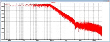
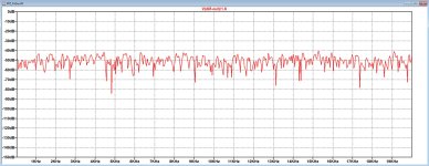
I processed in my model the first 262.144 samples from L and the same amount of 262.144 samples from R, or 8 blocks of each from a DSD256 .dsf file holding a 1Khz 0dB signal
But still no trace of the recorded 1Khz signal, but instead a huge amount of noise, see attachments.
I have tried with and without byte reversal, but without any success so far.
When playing this file over my audio set, it seems to work as expected.
That's why I have made 3 control files, one with 1110 1110 etc. to get maximum DC output level.
One with 0101 0101 etc. to get zero output
And one with 0001 0001 etc. to get minimum DC output level.
Note that this was sent from left to right, so with MSB first !
All three files work flawless giving resp. a seemingly noisefree 2.56Volt, zero Volt and -2.56Volt, exactly as it should be, so the model seems to be working properly
Still have no idea how to proceed but to proceed taking a next series of blocks, a rather cumbersome job.
Hans
Attachments
I found a bug in the program attached to post #763. It's a program that generates a non-repetitive silent DSD512 .dsf file. With small modifications, the Pascal program can also generate a tone. When calculating the data chunck size and the file size, I forgot to account for the fact that the program produces stereo files. Most .dsf playing programs will just ignore this, but I've corrected it anyway, see the attachment. When you change the extension from .txt to .pp, it runs under Free Pascal Compiler. Whether it produces useful output may depend on the endianness of the computer.
Attachments
@ThorstenL & MarcelvdG : Thank you both for your feedbacks! I look forward to reading more into what you have written, however, today I will be off for a week-long Easter vacation and I will not be back until sometime late next week. All the best for your Easter 😉
Jesper
Jesper
At 96kHz PCM sample rate the bit clock frequency of PCM2DSD is 12.288 MHz.
There are two simple workarounds on the digital side, both of which suck:
1. Correct for the PCM2DSD offset. The peaks then shift to the frequencies of the harmonics, so you will have harmonic distortion rather than weird-clusters-of-peaks distortion.
2. Add an offset large enough to shift the big peaks outside the frequency range of interest. This is actually a very often used workaround, but it hides rather than solves the issue: play a bass note that is just a bit stronger than the offset and the peaks come sweeping through the audio band again.
Marcel,
When you try the dac with your PWM8 modulator, is that being clocked at some sub-multiple of 27MHz, or it it derived from some standard audio clock frequency?
When you try the dac with your PWM8 modulator, is that being clocked at some sub-multiple of 27MHz, or it it derived from some standard audio clock frequency?
It was clocked at 27 MHz for my experiments with an FPGA module, but slower when bohrok2610 played a .dsf file generated with my Pascal program. I hoped he could play it at a DSD512 rate (22.5792 MHz), but due to some hardware limitation he had to resort to DSD128 (5.6448 MHz).
The algorithm is not very suitable for rates below DSD256, but it was good enough to see that the distortion products were gone. The quantizer runs at one eighth of the clock frequency, so the noise shaping gets poor at low rates.
The algorithm is not very suitable for rates below DSD256, but it was good enough to see that the distortion products were gone. The quantizer runs at one eighth of the clock frequency, so the noise shaping gets poor at low rates.
Then may I ask if that version of the Pascal file is one you are sharing? Its that I am curious about it, but not curious enough to build your FPGA project.
It's the program of post #2610, but with the constant DSD set to a smaller value, with the amplitudes set to non-zero values (0.0005 for -60 dB DSD) and with the data chunk and file size calculation bug still in there.
If you should want to use the program for music rather than test tones, like a software PCM to DSD converter, you would have to add a PCM .wav file reading routine and some sort of software interpolation filter. Maybe a very rudimentary one could do if you would only use it for high sample rate PCM (/do the first interpolating stages with another program).
The idea behind the modulator is explained in my Linear Audio valve DAC article.
Last edited:
Made yet another version of Marcel's dac board, This one only differs in having added u.fl test points for clock and data signals going into the shift registers, test points for things like scope grounds, and test points for both Vref supplies. The test points can be used to monitor existing signals, or else used to inject external signals if some upstream resistors are removed first. Also, Marcel has reviewed the Gerbers and said they look okay.
Attachments
- Home
- Source & Line
- Digital Line Level
- Return-to-zero shift register FIRDAC