Hi,
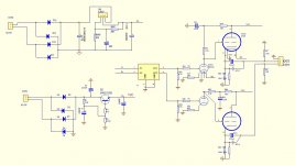
I have build headphone amp using E88CC and 6N5P
https://world.taobao.com/item/38864...=a230r.1.14.172.SsU0zc&ns=1&abbucket=5#detail
However I have a lot of good 6SN7 tube can I use adapter to use 6SN7 instead of E88CC?
The voltage on plate is around 90VDC.
Do I have to change plate resistor (47K resistor to be 1K) to lower value to make more voltage around 150VDC same voltage as 6N5P?
The adpater is here:
6V 6 3V 6SN7 6SL7 to 12AU7 12AX7 Tube Adapter Socket Converter One Piece | eBay
Thank you very much.
Attachments
That adapter is for 12AX7 etc. E88CC has different heater wiring.
The documentation does not tell if it can be used.
What is the +Ub of your amplifier ?
Sorry but I can not "interpreat" this. Can somebody ?
The documentation does not tell if it can be used.
What is the +Ub of your amplifier ?
The voltage on plate is around 90VDC...
Do I have to change plate resistor (47K resistor to be 1K) to lower value to make more voltage around 150VDC same voltage as 6N5P?
Sorry but I can not "interpreat" this. Can somebody ?
Ra can be about 27-33 kohm, but you can try, that plate current of output tube must be the same. It current depends from Ra. You must change the heater legs.
As others have stated, e88cc and other 6dj8 types are 9AJ base, ecc83/12ax7 etc are 9A base. That's the wrong adapter.
You want this one: 6SN7 6SL7 to ECC88 6DJ8 6922 6N11 Tube Adapter Socket Converter One Piece | eBay
You want this one: 6SN7 6SL7 to ECC88 6DJ8 6922 6N11 Tube Adapter Socket Converter One Piece | eBay
Where did you get that +Ub is 90 V ?
OP wrote something, not clear to me, about 150 V.
Ya, I misread, 90V is on the plate, so I must reconfigure again.
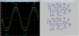
Here is 250V supply sim, both still very close, except the gain.
Attachments
Last edited:
Thank you for all advice from all of you.
There are a lot of kind man in this forum.
Thank you so much.
There are a lot of kind man in this forum.
Thank you so much.
My transformer is 6.3VAC & 145VAC
6.3VAC will convert to 6.3VDC
And 145VDC will bridged to 170 VDC.
I measure the voltage of Anodes of these 2 tubes
I got 170 VDC for 6N5P
I got 90 VDC for E88CC.
So What I curious is 90VDC is too low for 6SN7?
170VDC was drop by only 47K resistors
IF I omit this 47K resistors so E88CC anode voltage will be the same as 170VDC.
Which I think will operate 6SN7 better.
Am I correct?
IF I omit this 47K resistors so E88CC anode voltage will be the same as 170VDC.
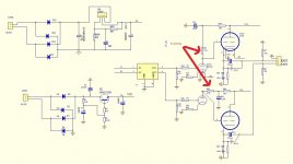
Omit or bypass? Either way, it won't work. If you bypass the 47k resistor, true the 6SN7 anode voltage will be the same as the high voltage supply (minus the voltage dropped on the RC filter).. but so will the grid of your 6N5P, rendering it useless (and possibly permanently damaged).
What you want when you change to 6SN7 is to keep its anode voltage to 90V so that you won't mess the bias for the 6N5P. As Koonw pointed out, that is doable by keeping the 47K and changing the cathode resistor to 820R. However, i prefer to flow more plate current by:
1. Reducing 47k to 18k (this shows as LR3 and RR3 on the schematic). Preferably 1W with 0.5W as the minimum.
2. Replacing RR4 and LR4 with 470R (or smaller just to ensure we don't drop too much voltage over it.. we need all the voltage we can muster. Power supply hum is already minimum as we have Q1 capacitance multiplier).
3. Changing the cathode bias resistor to 470R (LR5 and RR5).
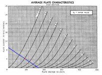
This way, you should get about 90V on the 6SN7 anode while flowing about 4.4mA of current. (170V on top of the 18k resistor and 90v on the other end = 80v across divided by 18k = 4.4mA). A bonus feature is you just barely avoid the non-linear part of 6SN7 plate curve.
As you can see above, 90VDC is still workable for 6SN7.So What I curious is 90VDC is too low for 6SN7?
Attachments
Dear Mr. Ballpencil,
Thank you for your advice.
I post the picture.
Is it correct?
Can I advise you here? I think he is trying to improve the input stage, as changes in input stage affects the output stage since it's directly coupled you may not get what you really desired. You have to wait for him or listen to other advice too or figured out yourself.
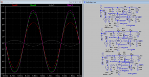
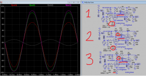
Anyway, you can look at the 3 sim data here to help you figure out, even only sim, it can be quite useful tool for making decisions, you agreed?
Attachments
Last edited:
Is it correct?
Yes, that's just correct. Koonw also showed something close to what i mean on his last post (the bottom circuit). He just didn't change the 4K7 RC filter resistor for the input stage so we end up slightly lower than 90V. If we reduce this to 470R, we should arrive somewhere around 90V on the 6SN7 plate. 470R and 22uF still works out to cutoff somewhere 15Hz, which is low enough to help reduce power supply ripple.
I think he is trying to improve the input stage, as changes in input stage affects the output stage
Yes.. this is pretty much it. I'm trying to keep the 6SN7 working in its linear region without disrupting the output stage. I happen to have a similar circuit in my sim collection but i only have 6N8S model (which is said to be equivalent to 6SN7) and 6AS7 (equivalent to 6N5P/6N13P). As we can see, we do arrive somewhere close to 90V on the 6N8S plate if we reduce 4K7 to 470R.
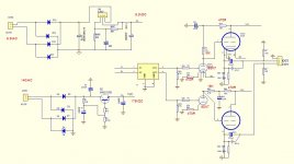
One possible problem to your plan is heater power supply. ECC88 needs only 300mA while 6SN7 needs 600mA. I notice that your heater supply is regulated using LT317. Is this only for the input tube? 6N5P needs 2.5A of heater current while LT317 is only capable of 1.5A so i'm guessing the 6N5P heater is powered somewhere else? If yes, the LT317 should be able to handle the extra current needed by the 6SN7. Just pay attention to the heatsink. You may or may not need to increase the size.
Attachments
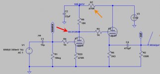
Plate 90V is just too high to properly bias the output tube. In order to prevent premature clipping, have to increase the bias (to about -2V), you need to lower the plate voltage not raise it, but you did just the opposite! And you're not talking about the sim of same tube model? My advice for this area will end here, elsewhere I haven't look, it may have other problems as you pointed out.Yes, that's just correct. Koonw also showed something close to what i mean on his last post (the bottom circuit). He just didn't change the 4K7 RC filter resistor for the input stage so we end up slightly lower than 90V. If we reduce this to 470R, we should arrive somewhere around 90V on the 6SN7 plate. 470R and 22uF still works out to cutoff somewhere 15Hz, which is low enough to help reduce power supply ripple.
....
Last edited:
supernut's amp is already working with ECC88 and 6N5P (which is why he can measure the plate voltages) and now he wants to change the ECC88 to 6SN7. He mentioned the ECC88 has 90VDC on the plate.. so this is my target operating point for the 6SN7.. and yes Koonw, my bias is at -2V as you can see on the loadline i drew on post #12. Another way to see it: 4.4mA x 470R cathode bias resistor = 2V.
6N8S is equivalent to 6SN7. I drew the loadline using 6SN7's curve and when i plug in the same values to the 6N8S model, i arrived at similar operating point: 90VDC on the plate and around 4mA plate current. If it's up to me, i would chase higher B+ (somewhere around 220-250VDC, like your simulation). That would give good operating point for 6SN7 and 6N5P. Unfortunately, supernut already have the power supply parts and he's stuck with 170V power supply.
6N8S is equivalent to 6SN7. I drew the loadline using 6SN7's curve and when i plug in the same values to the 6N8S model, i arrived at similar operating point: 90VDC on the plate and around 4mA plate current. If it's up to me, i would chase higher B+ (somewhere around 220-250VDC, like your simulation). That would give good operating point for 6SN7 and 6N5P. Unfortunately, supernut already have the power supply parts and he's stuck with 170V power supply.
Thank you for both of you Mr. Ballpencil and Mr. Koonw
Thank you for both of you Mr. Ballpencil and Mr. Koonw
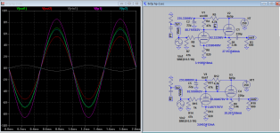
I see 3 simulation diagrams of Mr. Koon which consort to Mr. Ballpencil advice.
I have better idea. Due to I plan to build CARY AE-1 Preamp. My headphones are Sennheiser HD555, Momentum over ears, JVC HA-S500, Audio Technica ATH-M50S.
I think these headphones not hard to drive. I plan to do CARY AE-1 as both Pre amp and having headphone out. Can I?
Therefore my E100 Headphone (E88CC 6SA7) is no need to modified because I will focus to build CARY AE-1 to get better sonic instead)
Where to tab the Left and Right signal of the headphone?
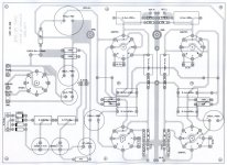
Please see schematic diagram.
I am not sure that I am on the right solution to use Cary AE-1 as both preamp and headphone amp?
Thank you for both of you Mr. Ballpencil and Mr. Koonw
I see 3 simulation diagrams of Mr. Koon which consort to Mr. Ballpencil advice.
I have better idea. Due to I plan to build CARY AE-1 Preamp. My headphones are Sennheiser HD555, Momentum over ears, JVC HA-S500, Audio Technica ATH-M50S.
I think these headphones not hard to drive. I plan to do CARY AE-1 as both Pre amp and having headphone out. Can I?
Therefore my E100 Headphone (E88CC 6SA7) is no need to modified because I will focus to build CARY AE-1 to get better sonic instead)
Where to tab the Left and Right signal of the headphone?
Please see schematic diagram.
I am not sure that I am on the right solution to use Cary AE-1 as both preamp and headphone amp?
Attachments
Mr. Koonw,
Which simulation is the best in your opinion?
I just saw the plate voltage is around 63V (top simulation) when 47K & 4.7K remain untouched. I might measure VDC wrong on E88CC plate.
oh I see, that is ok, you can measure again. You can use the simulation software LTSpice from Linear Technology, it is free, together you'll need to download tube model from this diyaudio site. I think LTSpice is very good for most beginner, very easy to drawn schematic diagram, some use the information for presentation directly. It can also export netlist to some common PCB software includes ExpressPCB. So you can get started. Please don't hesitate to ask if any question.
- Status
- Not open for further replies.
- Home
- Amplifiers
- Tubes / Valves
- Replace 6SN7 to E88CC on HP amp 90VDC plate capable?