How about this: "Panasonic HFQ series. These capacitors boast good ESR and DA performance in a reasonably-sized package and don't cost as much as earlier high-performance electrolytics."
Well I still think you can lower the DC in the output so that you can use rating of 200-250V which is maybe easier to get. See R13 and R15 on bottom sch. Maybe your PCB is not exactly the same as this sch.
Attachments
Last edited:
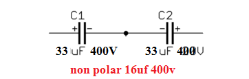
400V capacitor is fine I have about 10 units of Rubycon SXW 33uF 400V.
I might connect in series (negative polar together) to make them non polar.
I might connect in series (negative polar together) to make them non polar.
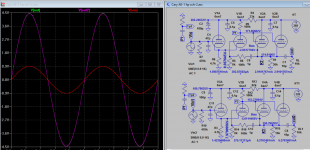
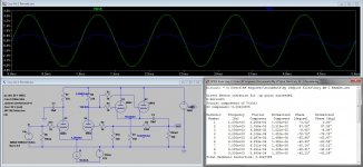
Had some time to kill at work so i played with LTSpice and made (what i believe is) an improvement over that Cary AE-1. It follows the basic topology but some changes are made to overcome the flaw i found. Unfortunately, i just realized that supernut already has the PCB for this and the changes i made maybe quite difficult to implement. Anyway, my feet are already wet it so here it is..
Some improvements:
- Added missing grid stoppers
- U4 no longer flows the trickly 300 microamps (!) of plate current. It's now increased to 5.2mA. This will help to drive the parallel cathode follower input capacitance
- U3 shares the same Vak as U4 and flows equal plate current
- The parallel cathode follower now flows 10mA of current, instead of the original minuscule 3mA: better drive of long interconnect cables and stray capacitances -- improved high frequency
- CCS instead of shared cathode resistor for the input stage. This alone improves THD by an order of magnitude. It's now 0.0027% with 2Vpp on input. I don't think THD this low will get you that tube sound, though. Might as well use an op-amp 😀
Attachments
Thank you so much Mr. Ballpencil for spending your time to help me revised cary ae 1 diagram
I will try hard to learn from your messages. I have not understand some part in circuit. I will ask you when i have time in Russia trip.
I will try hard to learn from your messages. I have not understand some part in circuit. I will ask you when i have time in Russia trip.
Dear Mr. Ballpencil,
Can I just cut the PCB Line by using cutter and hard wire new Resistors & Capacitors on the old PCB?
I can't create new PCB. I just copied from Web.
Do you have an actual size PCB? I will make new one.
Thank you.
Can I just cut the PCB Line by using cutter and hard wire new Resistors & Capacitors on the old PCB?
I can't create new PCB. I just copied from Web.
Do you have an actual size PCB? I will make new one.
Thank you.
Can I just cut the PCB Line by using cutter and hard wire new Resistors & Capacitors on the old PCB?
Sure, why not. That's how i would do it. Just make sure the grid stoppers are as close to the pins as possible. Soldering them directly to the pins is a good idea. I don't have actual PCB size.
The red box you asked on post #66 is called constant current source (CCS). I won't explain about it as google is just a click away but basically it forces the total sum of current that flows through U3 and U4 to be constant. You can make CCS using LM317 voltage regulator IC. See here LM317 / LM338 / LM350 Current Regulator Calculator and Circuits
LM317 needs at least 4V between the Vin and Adj pin. The -12V Vbias will provide you with this requirement. The cathodes of U3 and U4 are already at 4.36V so it maybe tempting to connect the LM317 straight to ground without Vbias but input signal will reduce this 4.36V and it will stop the LM317 to work properly.
I put -12V Vbias as i thought about using the same power supply to power the heaters for the 6SN7 (put the heaters in series). It doesn't really have to be -12V. It can be as low as -3V which can be provided by two simple AA battery. Why? Because 4.36+3V = 7.36V. This is high enough to keep the LM317 CCS working even with some input signal.
I forgot to draw it but there should be a diode between U4 plate and U1+U2 cathodes. Diode anode goes to U4 plate. This is a safety diode that prevents your grid from damage during first starts. It can be the ubiquitous 1N4148.
Oh! Mr. Ballpencil.
Thank you so much. I have to take lot of time to study. It is quite difficult for a guy like me who have just start studying electronic & Tube. I will try to understand every sentence you have written.
It is very challenge to me (have limited knowledge in Electronic) but I think it is so fun to learn. 🙂 I have plenty of time b/c E100 HP amp still save me as it perform as preamp now.
Therefore Cary AE-1 project is not rush. I still got better idea do you have any project of 4x 6SN7 which use 2X 5U4G So I can utilize all of my tubes. (I am now have 14 6SN7 4 E88CC 3 5U4G 4 12AU7 2 6SA7 300-0-300VAC 400mA 6.3VAC-0 4 amps 5V-0 5 amp 10H choke 100ma)
All I have are these. I hope I can make good tubes preamp if you can advise me, Mr. Ballpencil
The red box you asked on post #66 is called constant current source (CCS). <snip>
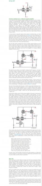
By improving the AE-1, you also removed the key feature of its design, that of the cathode-coupled amplifier, which certainly has a different sonic signature than the SS/CCS version.
I may have overlooked something but i see that there are only two advantages for this input stage topology (compared to the usual grounded cathode + cathode follower):
1. Low input capacitance (as we first see a cathode follower)
2. No phase inversion (which is, i admit, quite trivial but some do make it a big deal)
I tried to "improve" the AE-1 without removing these two advantages. Yes, it may have different sonic signature. supernut may or may not like it.. Something as low as 0.0027% THD in simulation may very well be an argument to just use an opamp.
If it were me, with 4 6SN7 i would just go with Aikido (yeah sounding like a broken record here) OR just skip an active preamp entirely as supernut already has the E100 hp amp if he ever needs line level amplification. Passive attenuator + channel selector is something i prefer more in his situation but he may just have the "itch" to build a tube preamp 😀
Assuming that the OP wanted the AE-1 "sound", the modified version may sound different, that's all... If he does not care, then he should give the improved version a try, since it does look better on paper.
Passive attenuator + channel selector is something i prefer more
I have ever tried to connect DAC directly to Rotel RB-981 (use volume control via Jriver Media Player).
It sounds not as warm as using E100 HP amp as preamp.
How to build passive attenuator + channel selector? Is it expensive or difficult to build?
Can you guide me or provide link of information?
If it were me, with 4 6SN7 i would just go with Aikido (yeah sounding like a broken record here)
Do you have a link of actual size PCB of Akido, Mr. Ballpencil?😀
Can I use 300-0-300VAC transformer? I don't want to buy one.
Dear Mr. Ballpencil,
http://ep.yimg.com/ay/glass-ware/aikido-octal-stereo-pcb-6.gif
This is the Akido that you mentioned, right?
I will try to create PCB.
http://ep.yimg.com/ay/glass-ware/aikido-octal-stereo-pcb-6.gif
This is the Akido that you mentioned, right?
I will try to create PCB.
Yes.. that's the Aikido Octal schematic you can follow. Even the component values are already worked out for you. I'm not one that usually use tube rectifier so i can't advise you on how to get 300VDC from 300VAC transformer using one. Just raise another thread to ask about this in particular.
You can make simple passive attenuator + channel selector very cheaply from Ebay. Just do a search. Attenuator is basically a fancy word for a volume control 😀 You can make one using any potentiometer. You have a lot to absorb, i'll leave you to it for now.
You can make simple passive attenuator + channel selector very cheaply from Ebay. Just do a search. Attenuator is basically a fancy word for a volume control 😀 You can make one using any potentiometer. You have a lot to absorb, i'll leave you to it for now.
I am not sure
Is this one call Passive Attenuator Preamp?
Passive Preamplifier with Dact Type Volume Attenuator for Hi End Audio | eBay
Is this one call Passive Attenuator Preamp?
Passive Preamplifier with Dact Type Volume Attenuator for Hi End Audio | eBay
- Status
- Not open for further replies.
- Home
- Amplifiers
- Tubes / Valves
- Replace 6SN7 to E88CC on HP amp 90VDC plate capable?