Dale/Craig
Regarding the interface:
) I think there should be separate interface, controler and relay boards.
That way you guys can produce a totally feature loaded controler board
and we can either use your interface board or hard wire our switches.
) have you guys tested any specific rotary encoders mechanical and optical?
Are there any quality of feel diferences? Eg the kind of difference
moving from a cratchy bourns pot to a silky alps blue?
regarding the controller:
) If your using 24 steps for volume control giving coarse 3db jumps, have you
considered having optional fine facilities with fine in 0.5 db steps?
You could even take this 24 course and 5 fine concept a stage further
and map all 138 combinations into the up/down control.
) A balance facility would be really useful.
) If you do load it with as many features as possible, we could just program
our remotes to use the facilities we require and are provided by the
relay boards we use.
) I'd be really keen to see some screenshots of how the interface
display / menu is progressing
and regarding the Relay Board:
) I'm keen to extend your design of relay board to include a parallel volume
ladder, and use different relays. I've used relays from pickering in the
past and they're of exceptional quality:
http://www.pickeringrelay.com/frames/main/112.html
) As your providing a microcontroller facility on the relay board, are you
going to make your PCB gerber files available so others can make their
own relay boards.
For anyone who hasn't seen it, I recommend looking at Mark Hennessy's preamp
design where he's employed a similar PIC programmed interface with display.
http://www.mhennessy.f9.co.uk/ He's also got some lengthy discussion on
the pga2310 (and 4 alternatives) chip which he uses.
Hello Guy's and Gal's
Dale, what ever you end up doing will be fine with me as it will be a lot better than I have now, which is nothing! 🙂
I am fine with the 72 relay solution, as you mentioned already, I have the option of loading the relay's as I need them. If done this way sure the relay's will cost a little more, but my initial investment will be more cost effective.
Please do not sacrifice your standards of quality to satisfy the masses. I think it behoves you to finish this project and develop a lower cost unit for those more budget conscious DIY'ers if demand warrants it.
Regards
Anthony
Hi Anthony,
I really needed your post. THANKS! I was starting to feel a bit defeated.
The quest to make everyone happy is nearly impossible.
Here are more questions:
1) Would it be acceptable to use pots to set LED backlight and LCD contrast? We could use some digital pots for the contrast and a PWM controller LED brightness level. This would allow software control.
2) For the encoder, I have tried the Grayhill 61C device < $20. It is a relatively inexpensive optical encoder with detents. It has a nice feel and can come with a switch. This would make a nice display interface. The switch/encoder would allow menu type options to be easily modified. I will leave in a RC filter for use with a mechanical encoder.
Remember, there will probably be at least two versions. Version 1 is like the Pass P1 in that it only uses 8 relays per channel. This version is NOT constant impedence and one cannot use a transformer. About 28 total relays.
Version 2 will be a series attenuator (Do people really feel that a Ladder is that much better. It would take twice the resistors). This version does have a lot of relays.
Best Regards,
Dale
This is looking very very good!
May I also suggest that you spend your time mostly on the control circuitry since this would allow us DIY'ers to do something signal wise as well 🙂
Also, regarding relays -- it is usually easier to sell something at a low cost. When people get into DIY mode, they do not seem to mind spending after they have started (at least that is the way with me). Thus unpopulated boards (or in my case better still just the controller with a documented interface I can use or Gerber files and/or schematic I can embed in my own project PCB) will be very useful in getting your business rolling.
Other things you might want to consider putting on the micro since you have already started so well:
1. Soft start circuitry (delay signals of say 0, 1 and say 3 seconds) to enable power supply.
2. DC sense -- ideally provide a number of sense points to enable sensing of DC levels OK + have a go/nogo signal go to output relay + visual warning if feasible. I would guess that 4 such signals will allow absolute sensing of DC at input and DC at output. Signal 2-1 and 4-3= offset which could be sensed as well.
Thanks and keep up the GREAT work
Petter
Dale,
Sorry! You must be suffering from information overload. What Petter had posted above would have been bare minimum for me, but you are correct that we can choose to leave out inputs and functions if we want to.
The design looks great and you have to stick with and not get side-tracked. Future versions can add more functions. I think the next exciting prospect is the design of the chassis that this is going into. If we can come up with a design that everyone is comfortable with it might be worth looking into someone fabricating it. ( So that Peter Daniel is not the only one with good looking chassis 😉 )
Regards,
Jam
Petter,
Your last post, is what I plan on doing, see post#44
I think I will have the relay board schematics completed by tonight, So I'll post the first draft, and then people can discuss the schematic directly.
Thanks,
Craig
Your last post, is what I plan on doing, see post#44
I think I will have the relay board schematics completed by tonight, So I'll post the first draft, and then people can discuss the schematic directly.
Thanks,
Craig
Craig,
I would be great if you could post mechanicals...size, dimensions etc. I am planning a chassis design for the unit. ( I probably need some coaching from Peter Daniel )
)
Regards,
Jam
I would be great if you could post mechanicals...size, dimensions etc. I am planning a chassis design for the unit. ( I probably need some coaching from Peter Daniel
)Regards,
Jam
Schematics now available for review
Hi guys,
Dale and I have posted the schematics in Acrobat (.pdf)
and Eagle schematic formats.
download here
Please refer to the schematic reference designators directly when requesting a design change, or if you have a question. If everything looks O.K. Dale and I will begin layout.
Thanks,
Craig Beiferman🙂
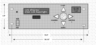
I wouldnt send this out to be machined, but I did a sketch of how I was thinking my finished project might look:
Schematics are posted
The latest schematics are posted.
Schematics
If you feel so inclined, the latest software is also posted on the download page.
On the control board, LCD backlight level and contrast adjust circuitry has been added and will be adjustable via the LCD interface. I have not mapped out the LCD displays yet, but will look at the McH... preamp.
There are now only four buttons and two leds, plus the encoder.
1) Mute
2) Bypass
3) Input select advance (direct available via remote)
4) Switch on encoder to enable "user interface"
Leds are +5V and IR commands detected.
The 8 bit LCD interface (plus 3 control lines)
RS232 interface
4 SPI interfaces
We are undecided on adding more unused I/O via some sort of I/O expander via SPI or I2C
Software
Dale
This will be my last, very low res attempt:
Well, I got it to stick grainy mono-chr0 that it is.
The triangular pushbuttons mount in round holes, they are by Happ Controls.
Ideally the rotary encoder would have a push- function allowing for menu selections by pushing in on the encoder shaft. I realize of course that this raises the cost of the encoder, but I think that if its within a few bucks it would be worth it. This functionality, like on my microwave oven, does wonders for increasing the intuitive nature of the user interface.
I will try to get the color image posted tonight.
Attachments
Ideally the rotary encoder would have a push- function allowing for menu selections by pushing in on the encoder shaft. I realize of course that this raises the cost of the encoder, but I think that if its within a few bucks it would be worth it.
like that one? just ordered some for less than one euro / Alps RK09710EL002
Attachments

Hi,
I'm not sure if you read these posts out of order.
"1) Mute
2) Bypass
3) Input select advance (direct available via remote)
4) Switch on encoder to enable "user interface"
"
Number 4 addresses the switch on encoder. I will look into the alps encoder. Some of these items are hard to source in small quantities. We usually look at US based distributors...
Best Regards,
Dale
Well,
I have to admit that I did read the post(s) about the encoder. Apparently I was so wrapped up with the greatness of my unique insight that I didn’t see you had already covered the issue. Most bothersome is that I did read and think about the posts.
I'll curb my big fat narcissism and pay better attention.
Please don't take it personally. I was being a overly defensive.
I do appreciate all of the suggestions.
We have been trying to address all angles with this design.
Best Regards,
Dale
I do appreciate all of the suggestions.
We have been trying to address all angles with this design.
Best Regards,
Dale
- Status
- Not open for further replies.