Chassis and Signal grounds
Here are a few more thoughts of grounding for audio:
http://www.jensen-transformers.com/as/as085.pdf
http://www.epanorama.net/documents/groundloop/groundlift.html
The first is a short paper by Jenson Transformer discussing the role of pin one in balanced audio signals. Assuming I understand them correctly, the paper argues that the pin one shield used on interconnect cables is used to carry the grounds between chassis.
This is significant because the chassis grounds and the signal grounds should only connect at a single point. This is important for the PC board layout as well as chassis construction. Ideally the chassis grounds and signal grounds will appear at two adjacent binding posts on the rear of the chassis. This allows for the chassis and signal grounds to either to be connected or floated depending on the users preferences and operating conditions. (a LP filter can also be inserted here)
This makes for a nice segway to talking about why telescoped grounds on inter connects. If we are trying to maintain a star point for the system ground, then each chassis should only connect to ground at one unique point. The earth ground on the power cord does this nicely. If we start interconnecting the chassis with XLR audio cables we introduce the opportunity to create secondary current flow between chassis in addition to earth. There exists a convention in which grounds are only interconnected at the output end of the connection. This works extremely well in large systems.
It is also important to recognize that not all manufactures view grounding the same way. Some equipment will not adequately separate signal and chassis grounds. This becomes a good news bad news scenario for us DIY types. The bad news is that initially such equipment can be a bear to get the best interface to. The good news is that it makes for some gratifying modifications that can result in an audibly cleaner signal path.
In a previous post I referenced a paper by Benchmark media http://www.benchmarkmedia.com/appno...caig/caig05.asp
Both this article and the nice one on EPANORAMA refer to partially floating interconnects. These use a cap and a resistor, in parallel, connected in series with the ground at the input connector. This forms a LP filter choking off RF and spurious noise but letting DC and ground currents pass. I’ve never actually tried constructing one ofthese, but there has been ore than once that I wished I had a set handy.
Enough digression and back to our project:
I like telescoping grounds. I like them a lot. If equipment has terminal strips for interconnection (crap, I seem to be warring out my aptop’s “L” key) Its quick and easy to make sure that everything is properly telescoped. However, if like me, when XLR’s are involved you are prone to grabbing pre-fabed cables, lifting he ground inside the male XLR is bothersome and often wont get done. Ground lift switches on the inputs? Expensive. Jumpers on the printed circuit that can float pin one from the female input connectors? Not too bad if you can convince the designers before they finalize the board layout. (Did I mention what a great job we all think your doing?)
Time to go.
Ciao!
APOX1
This unit would really benefit from a relay to set high/low range (reduce the value of the series pass element).
As I have noted before, most volume controls sound crappier the lower the volume setting since hardly any energy is transferred into the next stage.
Such a series pass element if implemented should autoswitch with the rest of the relays to enable a larger dynamic range on the volumen control.
Petter
Attachments
A final decision has been made.
There will be the following front panel connections.
1) Rotary encoder with pushbutton. Can be used for all options if so desired (this would include volume, input, and bypass, etc).
Mute may only be on remote or separate button.
2) Input select button(s). One or two buttons for input selection (prev,next). They will be mounted vertically above one another. These are also optional if you only want to use the encoder or remote to change inputs.
3) HT Bypass button (optional)
4) Mute button (optional) - available on remote. Will not be available via encoder/LCD interface (doesn't seem neccessary)
5) Power/standby button w/ two color LED (Yellow, Red)
An I/O line will be provided. This line will sink/source 25mA (5V)
You could switch an SSR, or a driver (darlington, fet, etc...) to power a mechanical or solid state relay
Of course, the power system is also optional.
There will not be a "Valid IR" led anymore. I will display "*" in LCD.
Seems like this solution would make almost everyone happy.
***Would not be able to do the volume control via buttons***
Sorry, this was the one sacrifice.
I will post some potential panel layouts...
Dale
Petter,
Since Craig will need to re-do the APOX-1 relay board with the SPI interface, I am sure that he can incorporate your suggestion(s). Really great ideas. Thanks!!!
Best Regards,
Dale
Since Craig will need to re-do the APOX-1 relay board with the SPI interface, I am sure that he can incorporate your suggestion(s). Really great ideas. Thanks!!!
Best Regards,
Dale

petter's ladder
I gave petter's ladder another thought for the re-design of the apox-1
I wrote a C program if anyone wants to screw with the values.
#include "stdafx.h"
#include "stdlib.h"
#include "math.h"
int compare (const void * a, const void * b)
{
if (*(double*)a > *(double*)b) return -1;
if (*(double*)a < *(double*)b) return 1;
return 0;
}
int main(int argc, char* argv[])
{
int i;
double temp;
double table[255];
double table2[255];
double rtable[8];
double rleft;
double rright;
double r2left;
double r2right;
double vin;
double vout;
FILE * pFile;
rleft = 1000;
r2left = 10000;
rtable[0] = 10000;
rtable[1] = 5000;
rtable[2] = 2500;
rtable[3] = 1250;
rtable[4] = 928;
rtable[5] = 494;
rtable[6] = 247;
rtable[7] = 123;
r2right = 10000;
rright = 1000;
vin = 1.0; // 1 volt input
printf("Hello World!\n");
for (i=0;i<255;i++)
{
temp = 0.0;
if (i&0x1) temp += 1.0/rtable[0];
if (i&0x2) temp += 1.0/rtable[1];
if (i&0x4) temp += 1.0/rtable[2];
if (i&0x8) temp += 1.0/rtable[3];
if (i&0x10) temp += 1.0/rtable[4];
if (i&0x20) temp += 1.0/rtable[5];
if (i&0x40) temp += 1.0/rtable[6];
if (i&0x80) temp += 1.0/rtable[7];
if (temp != 0.0)
{
temp = 1.0/temp;
vout = temp/(temp+rleft+rright)*vin;
table = 20*log10(vout/vin);
vout = temp/(temp+r2left+r2right)*vin;
table2 = 20*log10(vout/vin);
}
else
{
table=0;
table2=0;
}
}
// qsort (table, 255, sizeof(double), compare);
pFile = fopen ("rtable.txt","wt");
if (pFile!=NULL)
{
for (i=0;i<255;i++)
{
fprintf(pFile,"%f %f\n",-table,-table2);
printf("%d = %f\n",i,-table);
}
fclose (pFile);
}
else
{
printf("file would not open!\n");
}
return 0;
}
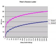
The values are not constant with binary steps. (But neither is the original APOX-1). So some sort of lookup table will probably be implemented to find the next closest step.
Attached is a graph of the dB steps per binary stepping of the relays. (The second curve is when you switch in the other
series resistor)
P.S. Dale added an opto-isolated output for the power control people. You will have to supply your own power to control your relays. The opto can handle 200mA at 35V (Is that sufficient?)
Thanks,
Craig Beiferman
I gave petter's ladder another thought for the re-design of the apox-1
I wrote a C program if anyone wants to screw with the values.
#include "stdafx.h"
#include "stdlib.h"
#include "math.h"
int compare (const void * a, const void * b)
{
if (*(double*)a > *(double*)b) return -1;
if (*(double*)a < *(double*)b) return 1;
return 0;
}
int main(int argc, char* argv[])
{
int i;
double temp;
double table[255];
double table2[255];
double rtable[8];
double rleft;
double rright;
double r2left;
double r2right;
double vin;
double vout;
FILE * pFile;
rleft = 1000;
r2left = 10000;
rtable[0] = 10000;
rtable[1] = 5000;
rtable[2] = 2500;
rtable[3] = 1250;
rtable[4] = 928;
rtable[5] = 494;
rtable[6] = 247;
rtable[7] = 123;
r2right = 10000;
rright = 1000;
vin = 1.0; // 1 volt input
printf("Hello World!\n");
for (i=0;i<255;i++)
{
temp = 0.0;
if (i&0x1) temp += 1.0/rtable[0];
if (i&0x2) temp += 1.0/rtable[1];
if (i&0x4) temp += 1.0/rtable[2];
if (i&0x8) temp += 1.0/rtable[3];
if (i&0x10) temp += 1.0/rtable[4];
if (i&0x20) temp += 1.0/rtable[5];
if (i&0x40) temp += 1.0/rtable[6];
if (i&0x80) temp += 1.0/rtable[7];
if (temp != 0.0)
{
temp = 1.0/temp;
vout = temp/(temp+rleft+rright)*vin;
table = 20*log10(vout/vin);
vout = temp/(temp+r2left+r2right)*vin;
table2 = 20*log10(vout/vin);
}
else
{
table=0;
table2=0;
}
}
// qsort (table, 255, sizeof(double), compare);
pFile = fopen ("rtable.txt","wt");
if (pFile!=NULL)
{
for (i=0;i<255;i++)
{
fprintf(pFile,"%f %f\n",-table,-table2);
printf("%d = %f\n",i,-table);
}
fclose (pFile);
}
else
{
printf("file would not open!\n");
}
return 0;
}
The values are not constant with binary steps. (But neither is the original APOX-1). So some sort of lookup table will probably be implemented to find the next closest step.
Attached is a graph of the dB steps per binary stepping of the relays. (The second curve is when you switch in the other
series resistor)
P.S. Dale added an opto-isolated output for the power control people. You will have to supply your own power to control your relays. The opto can handle 200mA at 35V (Is that sufficient?)
Thanks,
Craig Beiferman
Attachments
Hi Dale, Craig,
The project looks great. I’ll be signing up for one when I make up my mind.
I had a suggestion, sorry for waiting till the eleventh hour, I’ve been kind of busy. Would it be possible to implement an automatic, pre-set attenuation for each input. This would serve to equalize the volume output level as you switch between the different sources. It should only require some software additions and would be a very nice “creature feature”. Imagine not having to catch the woofer cone in lap during the THX splash.
Just a thought,
Rodd Yamashita
Jam,
the two color led was for:
the preamp is off 0 on the 0/1 button in the back,
the preamp in on stdby with powered active circuitry (of course) red led on
the pre-amp is on green led on
Dale,
I must say the mix and match of push buttons and rotary encoders are not my world's favorite solution. Jam had me convinced that the encoder was the only way to fly.
I guess, it's time to get a design artist involved into the panel sketching.
Grataku,
I am not sure what you guys have in mind.
If you don't want any switches, most functions will be available via the encoder/switch.
Did you want the power switch on the front or back?
This is a momentary switch, just like the others. I have implemented the "output" as an opto-isolated connection using a darlington type isolator. It can handle 200mA up to 35V.
An encoder looks like a switch? It is round (knob). Why do you guys hate the mix? This is your typical interface. A volume knob and switches. Or just switches...
I am going with the ITT PVA1O style switches. You can get caps in black, white, red. They come in round or rectangular look.
They have various height options as well.
Dale
Grataku,
I see what you say, my question is if the unit is in standby should you kill the display. I guess in your opinion the display stays on in standby, which is fine with me.
Dale, what Grataku and I ment about power (0/1) is that there be a mechanical power switch at the back to kill the ac ( this woud be an option), and up to the individual builder. There are IEC ac connectors that have switches built in. I would replace the power switch with a standby switch.
Regards,
Jam
sorry for beeing a pain,
- but what about two rotary encoders, selector on one side, volume on other, (power at rear).
This would make a symetrical layout, and no need to think about switches; quality, feel and look.
With this price-tag, I do not want to touch plastic!
Arne K
- but what about two rotary encoders, selector on one side, volume on other, (power at rear).
This would make a symetrical layout, and no need to think about switches; quality, feel and look.
With this price-tag, I do not want to touch plastic!
Arne K
I can turn the display off in standby mode...
I would rather not add another encoder, since I was using some built-in features of the PIC. I would have to write a bit of code to handle the second encoder and I would have to poll. Hmmmm, there are 4 bit output encoders...
Do you guys really, really, really want dual encoders?
I would assume that the second encoder would not need a switch.
If I go the dual encoder route, YOU WOULD NOT HAVE SWITCH INPUTS FOR INPUT SELECTION!!!
Should I eliminate the front panel switches for MUTE/Bypass. Both of these would be available via the remote. The bypass would be also be selectable through the encoder/switch interface.
The power/stanby switch would be optional...
Arne, you don't have to have any front panel switches with this scenario.
Dale
Arne,
You could be on to something here. You could use the swich on the volume rotary encoder to put the unit into standby and switch on the selector rotary encoder to enable bypass. Might work but could be dangerous. One or two switches might be required.
Regards,
Jam
You could be on to something here. You could use the swich on the volume rotary encoder to put the unit into standby and switch on the selector rotary encoder to enable bypass. Might work but could be dangerous. One or two switches might be required.
Regards,
Jam
Dual encoders..
I do not need any switch at all (exept in one of the encoders),
If there was "modes" (software).
Normally a straight volume encoder will be fine, and a selector-encoder (w.switch, for use in other / adjustment mode).

Arne K
I do not need any switch at all (exept in one of the encoders),
If there was "modes" (software).
Normally a straight volume encoder will be fine, and a selector-encoder (w.switch, for use in other / adjustment mode).
Arne K
BOARD IS SPLITTING UP
Hi guys,
I just made an attempt to layout the APOX-2.
Man was it ugly. I was very unhappy with the size of the board
and the huge number of traces.
There was no elegant flow of audio signals because of all of the relay controls lines. and if I spread out the components
for good audio flow, the board was just too big.
I was also dreading to do practically the same layout for both
the apox-1 and apox-2 for the input select lines.
SO! I have made a compromise that I think some people will actually appreciate when I am done. Here is what I am going to do.
I am going to seperate the input selection from the volume controller and make two boards. Also the input selection board will be only 4 inputs(like the APOX-1). (But wait!). I will make the input selection boards stackable for an unlimited number of inputs. (hee hee)
Dale and I have also choosen the PIC16F818 for the controller chip on the input select and volume controller boards. (in qty 25, the chip is only $1.85, and has an internal oscillator. So I don't feel bad about the need for extra microcontroller chips. And hopefully we can get enough board orders, that the NRE for the board manufacturer is not felt too much)
The input selection board will have output connectors, but if using stacked boards, only 1 output connector will need to be loaded (or you could use both outputs).
Also, I can make lots of different volume controllers, without worrying about re-doing the input selection board everytime.
(Yee Haw)
Thanks for your patience, Dale and I want to make something that will give you years of service, and not years of headaches wishing you had that one really nice feature.
Thanks,
Craig Beiferman
I could put the Power (standby) on the left (input select) encoder.
Are you worried about accidental pressing?
Thus, the only switches would be on the encoders themselves...
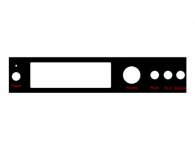
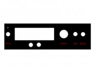
By the way, the pictures are not the front panel, just how I would layout the components on the PCB...
Are you worried about accidental pressing?
Thus, the only switches would be on the encoders themselves...
By the way, the pictures are not the front panel, just how I would layout the components on the PCB...
Attachments

How big of a knob are you going to use?
I need to leave room. How much spacing between the LCD and the center of the encoders...
Dale
I need to leave room. How much spacing between the LCD and the center of the encoders...
Dale
- Status
- Not open for further replies.