

jam said:Dale,
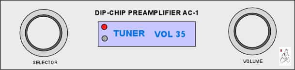
I would cut the display window oversize and glue a dark blue filter (plastic) behind the panel. The display and IR sensor are mounted behind this . Most manufacturers do this. If you need a sample please let me know.
Regards,
Jam
jam said:Final version?
Jam
For the Front panel, it would be nice to see something like a .125 thickness. As far as the lens goes, I plan on machining a lip into it so that it is perfectly flush with the front of the faceplate.
Hey Jam, it's not really a preamp is it? More like a fancy switch box.
🙂
Anthony

So...what's the story with this panel? You hit the selector and the thing comes out of stdby?
What about the LED how does it function with respect to the LCD? Red in stdby with the LCD off?
I still am not convinced of how nicely can the lens be attached to the panel in a matter that looks good and is mechanically child proof.
As far as thickness nothing less than 3/8 would be my choice. It makes no sense to have to take out a loan to buy APOX2 and then skim on the panel. 1/8 plate will be naturally very bent. We are going to have to fasten it in the center anyway, above and below the LCD like the Aleph0 chassis pict that Peter posted sometime ago. If you want to countersink a socket head screw, which looks SOOO good, we need a thick panel maybe even 1/2. Then we could think about recessing the knobs since the encoder shaft is very short. Anyways, I am running too far ahead. 😉
Arne,
We really like your front panel!
Grataku,
You will have two options for the standby switch.
1) On the selector switch
2) On a separate switch that will be located to the left of the selector encoder (you don't have to populate this switch)
Yes, the LED will be either a yellow/red or red/green bicolor. Depending on which way you install the LED, you can have it mean either.
Also, is my solution for the standby acceptable (darlington output opto-isolated) (200mA/35V) You can also buy higher voltage versions with the same package. NEC 2501
Note, I will also have switches for Mute and Bypass, but you don't have to use them or even populate them.
Craig and I had not originally planned on doing anything about the chassis. We are looking into options. At work, we have a CNC machine. We may try to convince ($) one of the machinists at work. We are not mechanical engrs, but we could probably get one to help us.
Dale,
drlngt option is ok by me.
Are the encoders going to be placed on a fixed position that correspond to the position on the panel or...? What about the pushbuttons?
The panel work would be nice but I can't design anything until I have the boards at hand.
drlngt option is ok by me.
Are the encoders going to be placed on a fixed position that correspond to the position on the panel or...? What about the pushbuttons?
The panel work would be nice but I can't design anything until I have the boards at hand.
Grataku,
The LCD, encoders, IR, LED, and optional switches will be located on the "bottom" of the board at pre-determined locations.
You are free to "hard-wire" these connections in order to mount everything exactly where you want it. You could mount the board anywhere and pick up the signals on the top of the board (plated through holes) or mount it upside down, etc,...
Trying to put connections for all of these components in multiple places would be tricky as I have lots of other circuitry to locate. If anyone has alternate thoughts, please state them now. I am finalizing the schematic and starting the layout as I write.
Best Regards,
Dale
Chassis options
Maybe making a complete 19" front-panel would be a great idea, as it can be mounted onto any chassis?
Then there is the Q: Silver or Black, maybe Titan, or Gold?
Perhaps Champagne...
Arne K

Maybe making a complete 19" front-panel would be a great idea, as it can be mounted onto any chassis?
Then there is the Q: Silver or Black, maybe Titan, or Gold?
Perhaps Champagne...
Arne K
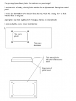
Thinking about how I might build my own chassis, I sent the attached letter to front Panel Express regarding my desire for a flush mounted display window. They replied, assured me that this is standard practice for them when specified. I think its likely that I’ll use them for at least the front of my chassis fabrication.
Sure wish I had access to a CNC shop at my office. Best I’ve been able to find, we don’t even have the capability at any of the labs. With any luck your machinist will also be an audiophile…
I have been wanting to build my self a small CNC rig for some time now. I figure an ENCO x-y compound modified for mounting a couple of servo’s w/ internal optical encoders… It will be wimpy, but I think the gen-1 machine will use a Dremil tool on a CNC z-axis. I have an idea for the mounting that will also allow the spindle to float for engraving.
Attachments
Board status update
I just wanted to give everyone a status update of the boards.
Dale made an update of the information about the board on the
dipchip electronics web site. APOX-2
Dale is almost done with his schematic. And has begun layout of the remote board. The toughest part is trying to place the LCD and the rotary encoder, IR, etc.. We are trying to work out the height issues with the components.
I have finished the schematic for the input selector board, and have done the first pass at a board layout. I'm really glad I broke up the input selector board and the volume board. It will allow for alot more options in the future for different volume control methods. I have also added a small feature on the input selector board. It involves two more relays that now switch out ground from the pre-amplifier during BYPASS mode. and the pre-amp inputs are now also grounded via a resistor during BYPASS mode.
This should keep any external pre-amp from oscillating.
I will begin the volume control board layout soon.
Thanks to everyone for the great front panel layout ideas. I think the two encoder idea looks great.
-Craig Beiferman
dipchip said:My last problem is what to do with the shield connectors on the XLR connectors.Craig Beiferman
For best RFI immunity, I suggest you follow the standard practice used in all modern PRO audio gear and connect the XLR shield and signal ground connections to the enclosure at the point where the signal enters the enclosure (the XLR connector itself). The signal grounds will be connected to your circuits ground at your star ground termination point. Don't be worried about potential ground loops by doing this. This is the standard ground and shield termination scheme used in audio mixers that have dozens of inputs (and mic preamps working at +60 dB of gain).
Neutrik sells XLR jacks that make the shield and signal ground connection within the connector itself, which is a good thing. Even a short jumper wire connecting ground to the chassis inside the enclosure can act as an antenna.
www.neutrik.com
Phil
I think that Haldor is very correct about the grounding technique for the microphone inputs on large audio mixers. I also think that it is worth considering that microphones present an interesting case for grounding not just because they present 60 or more dB of gain at the input, but also because the microphone does not connect to a separate power source. It might be argued that these mixers will often be connected directly to other equipment such as guitar amplifiers, tape machines, radio receivers and other mixers. For my own work I try to have a large assortment direct boxes and isolation transformers for these interfaces. Most direct boxes sport a ground lift switch exactly for this reason.
For our purposes some of this will become a highly academic discussion. With a couple of pieces of gear, plugged into the same power source, just a few feet apart, its tough to noticeably screw it up. I would not however recommend connecting signal and chassis ground together at the input XLR connection. My concern is that the placement of multiple chassis and signal ground points instead of a single star point, is that this can aid in the return of AC line current induced noise into the audio signal. AC noise filters almost always return noise to ground.
I know I can be very flexile about grounding topology. I’ve posted this stuff both in the hopes of stimulating interesting conversation. I am also hoping that we can get a PC topology that will allow us each to meet our needs with minimum application of the exacta knife to a nice new PC board.
-Dave
Haldor and Da5id4vZ,
The reason I was confused, is there are people who are insisting that they want the Left and right grounds seperate from one another, And the current input select relays completely disconnect all unused equipment (including grounds.)
I have seen some pro audio equipment
http://www.placetteaudio.com/passive_line.htm](like this one)[/URL] use this scheme.
That also completely dissconnect the unused equipment.
In order to try to satisfy everyone, This is what I'll do.
I will connect all of the Neutrik shield ground pins together on the board. I will then provide a place for a resistor (or short)
from the shield ground to both the LEFT signal ground and the RIGHT signal ground. This way, everyone can do what they want.
Is this method satisfactory?
Thanks,
Craig Beiferman
dipchip said:
In order to try to satisfy everyone, This is what I'll do.
I will connect all of the Neutrik shield ground pins together on the board. I will then provide a place for a resistor (or short)
from the shield ground to both the LEFT signal ground and the RIGHT signal ground. This way, everyone can do what they want.
Is this method satisfactory?
I don't think so...everything then becomes linked together, what if one wants to use RCA? It would get even worse. That wouldn't really satisfy Haldor either. I think he wants XLR with internal connections to gnd.
I say lets keep it flexible, a dual mono with the ground running near the back panel and pads to connect both chn together and a big pad to make a chassis connection directly to the back panel with a little Cu bracket or something.
As long as the gnd line is close to the chassis there are no long ground wires floating around that leak gnd noise into the chassis it should be ok, even for Haldor standards. 😉
I'm confused about the Chassis Gnd
Hello all,
I am confused by some of your posts as to exactly what you want for the chassis GND. (Some want the chassis shorted to the grounds, some people don't, I thought I had a good compromise, but maybe I don't understand whats going on!)
I have posted my latest input select board schematics
in .pdf format
When explaining what you need, please explain using the reference designators from the schematics, what exactly you want.
I want to get to the best solution for everyone. (I couldn't bear a exacto blade touching the board. )
-Craig Beiferman
Based on my inability to find a PCB mounted switch that comes close to matching the encoder height, I have decided to just put solder pads (or .1" headers) on the PCB for the "optional" switches. One can choose from the myriad of panel mount switches and put them wherever they choose. I will still have the encoders and LCD mouned directly on the board.
This will also make the board smaller.
How does placing the encoders 3" on center from the LCD display sound to everyone. You could use 3" diameter knobs and still be 1.5" from the display. With smaller knobs, they would not seem too far away.
Dale
This will also make the board smaller.
How does placing the encoders 3" on center from the LCD display sound to everyone. You could use 3" diameter knobs and still be 1.5" from the display. With smaller knobs, they would not seem too far away.
Dale
- Status
- Not open for further replies.