Dale, we are getting closer and closer to a final design, thanks for doing the hard work and listeing to your demaning customers.
Now it would be the right time to put some dimensions down how big is the LCD? I think the knob could be anywhere from 1 to 1.5 inches. I would still claim the usefulness and looks of having an on/stdby button on the front.
Now it would be the right time to put some dimensions down how big is the LCD? I think the knob could be anywhere from 1 to 1.5 inches. I would still claim the usefulness and looks of having an on/stdby button on the front.

Hi Grataku,
Would you mind if the second encoder switch (input selection on left) was the power standby?
The LCD is an Optrex DMC-20261
116mm x 37mm (4.5"x1.5")
Would you mind if the second encoder switch (input selection on left) was the power standby?
The LCD is an Optrex DMC-20261
116mm x 37mm (4.5"x1.5")

Yeah, I like it!
Only thing i'm a bit worried about is the on/st.by on the encoder.
Would rather have it as an optional separate?
And maybe mute/dim as push-on-volume?
And mode-select on push-on-selector?
Arne K

Only thing i'm a bit worried about is the on/st.by on the encoder.
Would rather have it as an optional separate?
And maybe mute/dim as push-on-volume?
And mode-select on push-on-selector?
Arne K
Hi Guys,
Craig and I have decided to drop this project.
Just kidding!
We have decided to make a few changes. Tonight, I am going to put together all of our notes and update our website.
As far as interface options, remember, we can do a lot of stuff in software to re-map functionality. We can also provide place holders for extra functions that can be enabled through software or by specialized versions. We have decided to go all I2C. This way we can free up more I/O lines. I may use some of these for option selection...
Stay tuned......
Dale
Dale,
You almost gave me a heart attack!
The IR sensor cound be hidden in the display window. This should allow for a cleaner look.
Regards,
Jam
You almost gave me a heart attack!
The IR sensor cound be hidden in the display window. This should allow for a cleaner look.
Regards,
Jam
remote the IR
Um,
Perhaps the IR sensor could be remote located and connected to the rear of the chassis to allow for optimum placement.
Um,
Perhaps the IR sensor could be remote located and connected to the rear of the chassis to allow for optimum placement.
I book marked this URL from someone else’s thread:
http://www.frontpanelexpress.com/
I havent used them myself, but the prices and online photos look good.
A rectangular hole for the LCD and IR would be covered from the rear with a tinted plastic.
("covered from fear" spell check is dangerous in the hands of the illiterate!)
http://www.frontpanelexpress.com/
I havent used them myself, but the prices and online photos look good.
A rectangular hole for the LCD and IR would be covered from the rear with a tinted plastic.
("covered from fear" spell check is dangerous in the hands of the illiterate!)
The IR sensor will be placed on the board so one could mount it and have it viewable (to an IR) from the front panel.
Basically, the board will have non UI components all located on what you would call the top of the board. The UI components will be mounted on the back of the board. You will have the option of remote wiring anything or everything. You could mount the board on the bottom and not on the front if you so choose. In order to make this project do-able for average builders, we will provide a basic layout that meets most people's needs/desires. One can choose to modify as one sees fit.
Here is one thought that we should all agree on.
"There is no way to satisfy everyone"!
I used the frontpanelexpress to do my quick and dirty pictures. I have not used their service, but may try it out. They have a USA site.
Dale
Dale,
I would cut the display window oversize and glue a dark blue filter (plastic) behind the panel. The display and IR sensor are mounted behind this . Most manufacturers do this. If you need a sample please let me know.
Regards,
Jam
I would cut the display window oversize and glue a dark blue filter (plastic) behind the panel. The display and IR sensor are mounted behind this . Most manufacturers do this. If you need a sample please let me know.
Regards,
Jam
Jam,
I just looked on my cheapo receiver in my office. I see the IR right beside the LCD. Quite hidden. I will position the IR detector so that it is roughly centered vertically in the LCD and on the Left side (of course half of you will want the right side )🙄
I just looked on my cheapo receiver in my office. I see the IR right beside the LCD. Quite hidden. I will position the IR detector so that it is roughly centered vertically in the LCD and on the Left side (of course half of you will want the right side )🙄
Dale,
Actually left is better, because the volume knob is usuall on the right and most people seem to put their equipment on the right, hence less chance of missing the sensor. But if you have two knobs.....
Regards,
Jam
P.S. Mounting the sensor next to the display, like you say, is the way to go.
Actually left is better, because the volume knob is usuall on the right and most people seem to put their equipment on the right, hence less chance of missing the sensor. But if you have two knobs.....
Regards,
Jam
P.S. Mounting the sensor next to the display, like you say, is the way to go.
jam said:Dale,
I would cut the display window oversize and glue a dark blue filter (plastic) behind the panel. The display and IR sensor are mounted behind this . Most manufacturers do this. If you need a sample please let me know.
Regards,
Jam
I don't know about starting to glue stuff...how does this IR sensor look like? If it's like an LED then it could just be flush mounted to the panel, maybe a little snap on lens could be located so once the correct size hole is made you are home free.
At this point I lost track of what everyone is talking about. The on/stdby switch being part of the input selection?? I think we should let the dip chip guys do their magic and let them button down some type of configuration.
Great job guys!!!!
I like simplicity in my components....
The decision to go with two encoders is great! Very clean...
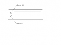
What about placing the standby led and the IR sensor one above the other to the left of the display hidden behind the glass?
When the unit is in standby mode, the led would be on and when the unit had power the led would go off and the display would be lit... This way one only needs to glance at the middle of the unit...
I would mount the standby led on top and the IR sensor on the bottom...
Thanks for the hard work - I can't wait to get one of these!!!!
I like simplicity in my components....
The decision to go with two encoders is great! Very clean...
What about placing the standby led and the IR sensor one above the other to the left of the display hidden behind the glass?
When the unit is in standby mode, the led would be on and when the unit had power the led would go off and the display would be lit... This way one only needs to glance at the middle of the unit...
I would mount the standby led on top and the IR sensor on the bottom...
Thanks for the hard work - I can't wait to get one of these!!!!
Attachments
- Status
- Not open for further replies.