@nihtila.
Today I found the time to measure crosstalk of the BPBP with VolCB
In my case the loudest setting is +6dB and I went measuring until -20dB, a range of 36 dB in steps of 2 dB.
I used the same 10 Khz as you did and found that crosstalk was in all these settings between 105 dB and 110 dB when using a constant output of 500mV Rms at all volume settings.
So the varying crosstalk figures that you measure, seem to have nothing to do with the principle of using a Gndr and Gndl connecting, but everything with the layout of the PCB.
Excuse me for asking, but are you sure you haven't interchanged Gndr and Gndl ?
Hans
@nihtila.
Today I found the time to measure crosstalk of the BPBP with VolCB
In my case the loudest setting is +6dB and I went measuring until -20dB, a range of 36 dB in steps of 2 dB.
I used the same 10 Khz as you did and found that crosstalk was in all these settings between 105 dB and 110 dB when using a constant output of 500mV Rms at all volume settings.
So the varying crosstalk figures that you measure, seem to have nothing to do with the principle of using a Gndr and Gndl connecting, but everything with the layout of the PCB.
Excuse me for asking, but are you sure you haven't interchanged Gndr and Gndl ?
Hans
Thanks Hans, this is both good and bad news 🙂 I also noticed in my measurements that at least it is not the relays alone.
And I never suggested that the principle of GNDR/GNDL would be wrong, just first thought it would be the relays.
I just can't figure out what is it exactly in my layout causing the issues. Have tried various things to reveal if it is capacitive or inductive coupling or what but don't see any difference. Your question regarding interchanged ground references is relevant but it is not the case here. It would cause more crosstalk and also my figure gets worse with higher frequency so it is not common impedance coupling.
This seems really weird, I just get more confused the more things I try. Will probably need to have a break and try again in few days. It makes it even trickier to track down as it is not a massive flaw somewhere, we are still down 95 dB. This does not have any practical meaning but as an exercise and good learning opportunity, I want to understand what is causing this.
Do you have some documentation of this part of your PCB. Maybe I can find something.Thanks Hans, this is both good and bad news 🙂 I also noticed in my measurements that at least it is not the relays alone.
And I never suggested that the principle of GNDR/GNDL would be wrong, just first thought it would be the relays.
I just can't figure out what is it exactly in my layout causing the issues. Have tried various things to reveal if it is capacitive or inductive coupling or what but don't see any difference. Your question regarding interchanged ground references is relevant but it is not the case here. It would cause more crosstalk and also my figure gets worse with higher frequency so it is not common impedance coupling.
This seems really weird, I just get more confused the more things I try. Will probably need to have a break and try again in few days. It makes it even trickier to track down as it is not a massive flaw somewhere, we are still down 95 dB. This does not have any practical meaning but as an exercise and good learning opportunity, I want to understand what is causing this.
Hans
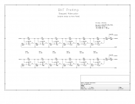
Ok, here is the whole schematics PDF and additional sheets. It is good to focus on the attenuator part. I have attached schematics PNGs of relevant parts, I populated a test PCB containing only these parts (orange rectangular): U3 and U4 + external components, and attenuator circuit without relays, I just shorted contact pins. Signal is fed on W1/W2 and W3/W4. There is no DC servo populated.
I will need to make the schematics clearer at some point, but the GNDL/R return from attenuator comes to the GNDL/R star point.
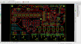
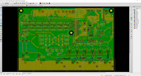
There are also layout captures. In addition to what is seen, there is ground plane/fill on bottom (green) layer.
I will probably make another even simpler test PCB to try some things, and cut some traces.
I will need to make the schematics clearer at some point, but the GNDL/R return from attenuator comes to the GNDL/R star point.
There are also layout captures. In addition to what is seen, there is ground plane/fill on bottom (green) layer.
I will probably make another even simpler test PCB to try some things, and cut some traces.
Attachments


Ok, here is the whole schematics PDF and additional sheets. It is good to focus on the attenuator part. I have attached schematics PNGs of relevant parts, I populated a test PCB containing only these parts (orange rectangular): U3 and U4 + external components, and attenuator circuit without relays, I just shorted contact pins. Signal is fed on W1/W2 and W3/W4. There is no DC servo.
Give me a few days.
Hans
@Nihtila,
You must have used a multilayer.
I would like to see the layers below the switching lines.
Because the main cause that I see is:
The distance between layers in a multilayer is quite small, therefore a relatively large capacity exists between traces and planes below giving unwanted cross-coupling.
This can be relatively easy checked on one side of your amp by desoldering the 6 resistors that are connected to Gndref_R and solder them back in upright position with only one side on the solder pad going to line 7 of the relay.
Then connect all the uppers sides of the upstanding resistors with a wire that ends at the GNDR point, just where the PCB trace ends now also.
This is just a simple non-destructive test.
Hans
@Nihtila,
You must have used a multilayer.
I would like to see the layers below the switching lines.
Because the main cause that I see is:
The distance between layers in a multilayer is quite small, therefore a relatively large capacity exists between traces and planes below giving unwanted cross-coupling.
This can be relatively easy checked on one side of your amp by desoldering the 6 resistors that are connected to Gndref_R and solder them back in upright position with only one side on the solder pad going to line 7 of the relay.
Then connect all the uppers sides of the upstanding resistors with a wire that ends at the GNDR point, just where the PCB trace ends now also.
This is just a simple non-destructive test.
Hans
It is just a 2-layer board, bottom layer has ground fill along with few short traces, see attachment. 1.6mm PCB.
I have tried quite a lot of things on a populated test PCB where I can also do destructive tests, so I have tried to re-direct the GNDL/R current etc. None have improved the results so far. It does seem to be related to the amount of current flowing in GNDL/R, therefore the attenuation resistors.
But increasing distance to the ground plane is something I have not tried, I will try it next week. I still dont understand exactly how it would couple then. If it couples to ground plane, then it would couple to the other channel the same way? But shouldnt the ground plane being close kinda prevent this, keeping the coupled signal in a small area under the traces. I always use ground planes and prefer them even being closer than 1.6mm and never had crosstalk issues before. Somehow find this difficult to dive deep into as each channel is referenced to ground only at one point (but then again if it was ground-reference problem it would be common-impedance coupling and frequency-independent).
Thanks for the suggestion, will report if it reveals something. If you have more ideas what to try, even destructive (cutting traces etc), let me know. I have gone too far to give up on this!
Attachments
Those who have MAYA BPBP for IOS (with BLE module) may help us to test Android application which is in beta now.
Thanks in advance !
MAYA advanced preamplifier - Apps on Google Play
Regards,
Tibi
Thanks in advance !
MAYA advanced preamplifier - Apps on Google Play
Regards,
Tibi
@nihtila
Haven’t heard from you lately, did you book any progress
Hans
True, I could not figure out the root cause so I kinda buried it for a while 🙂 Well, not really, it has been in use while I have been doing other things.
But I should maybe get it back to bench and see things with hopefully fresh eyes.
Hi,
I am in the finishing stages of finishing the preamp with the maya control and have an issue with switching the powertransformer tru the standby relais that was included when I ordered my Maya.
Problem is there is a transformer hum when in standby. I am using a custom 2x13V 50VA torroidal transfomer. With the standard setup the relay in off position is parralled by a 100 Ohm/100nF combo. I dont like to mess with with mains power so i have some questions !-)
My questions:
-is it OK to switch a torroid transformer on one side instead of a double pole?
-can i remove the 100 ohm/100nF combo or would this fry the relay (it is rated at 10A @250V) in the long term?
-if not: suggestions for different values?
Thanks,
Gerben
Hi Gerben,
You may remove 100ohm resistor or 100nF cap. It is enough to remove only one.
At 50VA transformer these have no effect.
These are there to protect relay against contact flame at very high power transformers that surge lot of current at power on.
Regards,
Tibi
You may remove 100ohm resistor or 100nF cap. It is enough to remove only one.
At 50VA transformer these have no effect.
These are there to protect relay against contact flame at very high power transformers that surge lot of current at power on.
Regards,
Tibi
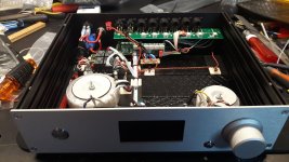
Hi,
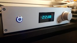
Some pics....
Edit: Pics dont show here...please right click and open in new tab....
I am really happy with the way it visually turned out. I lack real metalmachining skills nor equipment and everything was cut out by hand.
The sound, or lack of it, is really clean and detailed. On to building a Hypex power-amp !-)
Some pics....
An externally hosted image should be here but it was not working when we last tested it.
An externally hosted image should be here but it was not working when we last tested it.
Edit: Pics dont show here...please right click and open in new tab....
I am really happy with the way it visually turned out. I lack real metalmachining skills nor equipment and everything was cut out by hand.
The sound, or lack of it, is really clean and detailed. On to building a Hypex power-amp !-)
Last edited:
For those who have Maya with BLE module, mobile applications have been updated recently.
Main change is that now volume support touch and hold for volume up/down at 5dB/s and some small bugs have been cleared.
MAYA advanced preamplifier on the App Store
MAYA advanced preamplifier - Apps on Google Play
Regards,
Tibi
Main change is that now volume support touch and hold for volume up/down at 5dB/s and some small bugs have been cleared.
MAYA advanced preamplifier on the App Store
MAYA advanced preamplifier - Apps on Google Play
Regards,
Tibi
Hi,
Does the new Android App work with Firmware version 1.2? I'm asking since it wont find Maya when scanning.
Regards,
Gerben
Does the new Android App work with Firmware version 1.2? I'm asking since it wont find Maya when scanning.
Regards,
Gerben
This new Andrid app will work only with BLE module. Do you have BLE ?
Regards,
Tibi
How can i determine this?
Gerben,
You have the old module, that is supported only by android.
I have updated old apk to support touch and hold for volume up/down.
https://www.vicol-audio.com/img/maya/MAYA_ver2_2.apk
Please test and let me know.
Regards,
Tibi
You have the old module, that is supported only by android.
I have updated old apk to support touch and hold for volume up/down.
https://www.vicol-audio.com/img/maya/MAYA_ver2_2.apk
Please test and let me know.
Regards,
Tibi
- Home
- Source & Line
- Analog Line Level
- Remote Control for the BPBP