Salas,
Is it ok to put 0,22uF instead of 0,1uf for zobel network? It is just I have some of good quality under my hand. What would be the drawback of this?
Thanks,
To try that alter the Zobel's resistor to 0.22R also because otherwise making that cap higher alone it will just eat phase margin especially when the J2 mod is in use.
MSRF860G
Hi, Salas, thanks. I check it at mouser:
http://www.mouser.com/ProductDetail...=/ha2pyFadug3omNM3PhsKcUv9vr1Ix/SVZb1hKIlOQs=
It seems that the image is not right (three legs instead of two).
But I suppose it is the right product (with wrong image)? Thanks again.
Has the right listed data + datasheet when that image seems random
There is the plastic back version too (needs no insulator if mounted to cool)
http://eu.mouser.com/ProductDetail/...=/ha2pyFadujArylZXwS9EhgWjZ7sP/TnOdfCYpvS0Gc=
There is the plastic back version too (needs no insulator if mounted to cool)
http://eu.mouser.com/ProductDetail/...=/ha2pyFadujArylZXwS9EhgWjZ7sP/TnOdfCYpvS0Gc=
Soft recovery is good & insulated package is practical. This diode type is popular enough among diyers already I think. Especially in digital builds. But there will be other favorites also.
I was advised by an engineer at ON Semi that for circuits where noise and RFI were critical factors, the ultra soft recovery of the MSRF860 was the optimum diode choice. Since then I have used them a lot and have never been disappointed.
To try that alter the Zobel's resistor to 0.22R also because otherwise making that cap higher alone it will just eat phase margin especially when the J2 mod is in use.
Thanks Salas, thanks AndrewT for the answers.
BTW From AndrewTs post I can conclude that: "The bigger the capacitance of the Zobel cap, the lower the frequency at which current is drawn from Zobel".
In Salas SSLV the cap in Zobel network is 4,7uf-10uf, while in Reflector D only 0,1uf.
So, does my conclusion from AndrewT post explain why in Salas SSLV the quality/type of Zobel cap has much stronger impact in overall sound signature than in Ref D (if used to power gain stages)? - that is my experience.
Does this also imply that in case of Salas SSLV the bigger the capacitance of the Zobel cap the stronger impact it has on sound signature (because more current is drawn from it at lower frequencies)?
Thanks,
Last edited:
It holds in general that bigger Zobel cap means lower frequency of draw but in the total open loop analysis it works in conjunction with the whole circuit characteristics so the bandwidth can be still comparable in different designs with differently optimized Zobel values. Bigger capacitors have higher parasitic values in general.
It holds in general that bigger Zobel cap means lower frequency of draw but in the total open loop analysis it works in conjunction with the whole circuit characteristics so the bandwidth can be still comparable in different designs with differently optimized Zobel values. Bigger capacitors have higher parasitic values in general.
Thank you Salas for explanation.
BTW I found somewhere that for SSLV for some high enough capacitance e.g.: 47uF in Zobel the 1R resistor can be skipped? Is that correct?
If its a normal ESR electrolytic then the 1R should be a jumper link. Its another type of termination for less bandwidth that in some occasions it can be preferable.
Has the right listed data + datasheet when that image seems random
There is the plastic back version too (needs no insulator if mounted to cool)
http://eu.mouser.com/ProductDetail/...=/ha2pyFadujArylZXwS9EhgWjZ7sP/TnOdfCYpvS0Gc=
Hi, Salas,
Thanks. I am about to place order for them. Just realize I might also buy some caps and resistors for the anti-ringing snubber parts, Cx, Cs, and Rs, what would you recommend to go with MSRF860G? Thanks again.
WYAN
I can't recommend because the main variable for those values is your transformer. You got to do the lab thing to arrive in values. You must read the Quasimodo thread.
If its a normal ESR electrolytic then the 1R should be a jumper link. Its another type of termination for less bandwidth that in some occasions it can be preferable.
Got it. Thanks!
hi,
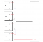
my dac needs +- 12 v in the digital side. can i use 4 x 6 v of ref-d in this configuration ?
(please see attachment)
can i use 8 vac from secondary of a transformer to get 6 vdc output from ref-d ? any drawbacks using this configuration ? does low output impedance matter for digital circuit ?
my dac needs +- 12 v in the digital side. can i use 4 x 6 v of ref-d in this configuration ?
(please see attachment)
can i use 8 vac from secondary of a transformer to get 6 vdc output from ref-d ? any drawbacks using this configuration ? does low output impedance matter for digital circuit ?
Attachments
It looks like it would work. Better use Schottky bridge diodes when from 8Vac to minimize DC loss. But its tight. If you will read back there was a small discussion with formulas on how to calculate margins for ripple & filter capacitor value vs Vac.
hi Salas,
it seems my AD1862 dac has a flexible digital power supply input. this could even be powered by 5 v ! but i need to trace the pcb to see if this powering something else.
sorry for being of topic but for analog side i need +- 12 vdc. is 56 VCT transformer the correct choice for +- 12 v of SSLV BiB ?
like this trafo ?
http://www.mouser.co.id/ProductDeta...2pyFadujjJWLMkzAozqnds%2bry%2bjnLqfwiHFtZMZo=
i'll PM Tea-Bag for pcb.thanks !
That's 2x23VAC which is much and won't work anyway because when you stack supplies you want them independent so to behave like batteries. I.e. one secondary and one diodes bridge for each section.
In your shoes I would use one magnetically shielded 15+15V (four secondary wires) 50VA trafo and two big REF-D that have own rectifications,. Then I would boost their Vrefs with LM329 and two Leds (one extra in the place for diode/resistor) to get about 12Vdc from each and stack them. Less stuff in the box.
In your shoes I would use one magnetically shielded 15+15V (four secondary wires) 50VA trafo and two big REF-D that have own rectifications,. Then I would boost their Vrefs with LM329 and two Leds (one extra in the place for diode/resistor) to get about 12Vdc from each and stack them. Less stuff in the box.
i just re-read the BiB build guide and max AC input is 36 v. sorry for that.
i don't think i follow you. where should i put LM329 ? could you give a simple drawing to get BiB work for 12 v ?
i don't think i follow you. where should i put LM329 ? could you give a simple drawing to get BiB work for 12 v ?
This is REF-D thread and I gave +/-12V simpler than 4x6V solution with REF-D also. We can chop off its no connection third leg and put the LM329 in Led1 position there with its cathode opposite to Led orientation. That could do for your digital section question. Bib can work to 12V with its trimmer, you don't need more than one breakable pcb of them and a 15+15V transformer. It has three sections, one bipolar and an extra positive. You break away the extra positive and keep it for another use. Max AC is one thing, power dissipation across the CCS Mosfet down to a much lower Vout from VdcRaw is a problem though. So we keep the transformer secondaries to enough for each occasion but manageable Vac.
ok, i understand this ref-d version but how much this ref-d version need ac voltage ? is 15+15 v for this ref-d or BiB ?
- Home
- Amplifiers
- Power Supplies
- Reflektor-D builds