800mohms seems a bit low for a small transformer.
Did you use PSUD2 to calculate that source impedance for you?
Hi, that is just an arbitrary number. I suppose it is just the resistance of the transformer's secondary and can be measured. Am I right? I will do another simulation later.
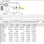
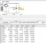
By the way, I simulate with transformer with 9V secondary and with 10,000uf capacitor as the first stage of filtering (as in flexy). The voltage across the CCS is really not 11.3V and depends on the current level. See the two attachment with 150mA CCS and 450ma CCS respectively.
Choke input smooth the voltage of raw dc a lot as expected and maybe I really don't need as high as 18V?
Thanks.
Attachments
PSUD2 will calculate that for you. You just click the icons in the correct order and the software takes you through some dialogue entry fields.Hi, that is just an arbitrary number. I suppose it is just the resistance of the transformer's secondary and can be measured. Am I right?
the output of a choke input filter is roughly 0.9* Vac when the current draw is above critical.I will do another simulation later.
By the way, I simulate with transformer with 9V secondary and with 10,000uf capacitor as the first stage of filtering (as in flexy). The voltage across the CCS is really not 11.3V and depends on the current level. See the two attachment with 150mA CCS and 450ma CCS respectively.
Choke input smooth the voltage of raw dc a lot as expected and maybe I really don't need as high as 18V?
Thanks.
I see you have 150mA through 10r twice, that accounts for 3Volts of drop.
Add that 3V to your 11.4V @ the output and you get 15.4Vdc, That's ~85% of 18Vac so you are in the same ballpark. PSUD2 should be about right for the values you have supplied.
Why did you change from 150mA to 450mA for the capacitor input?
Last edited:
Hi, thanks again.
I was trying to say that the raw voltage output of flexy (which use 10,000uf cap input) will differ with different CCS settings in the reflektor-mini.
I need to supply +-5V 20-50mA for soekris R2R DAC. So the CCS is set at 150mA. Need to figure out what is the optimal raw voltage supply for the mini. I may abandon flexy and use choke input instead.
Thanks again. 🙂
Salas,
tried to power reflector D build not used from long ago but It does not start - no lights
I measure all the dc voltage from smoothing cap after reactifiers at Vgs ccs mosfet
what Is your recommendation to look first
tried to power reflector D build not used from long ago but It does not start - no lights
I measure all the dc voltage from smoothing cap after reactifiers at Vgs ccs mosfet
what Is your recommendation to look first
Check the CCS is passing some/any current.
Start with a low input voltage with the output shorted.
The CCS current can be checked by measuring across the CCS resistor.
post1 has no sch. post18 takes me to the wrong post.
Start with a low input voltage with the output shorted.
The CCS current can be checked by measuring across the CCS resistor.
post1 has no sch. post18 takes me to the wrong post.
Salas,
tried to power reflector D build not used from long ago but It does not start - no lights
I measure all the dc voltage from smoothing cap after reactifiers at Vgs ccs mosfet
what Is your recommendation to look first
Check that the output connections are good first. If sense lines are not making contact it may appear dead.
Then do like Andrew said but better with the dummy resistor load if you still have it. Also check that the readable Vgs and Vbe are normal like 4V 0.6V in all fets and transistors indicating if they are all alive or some semi is gone.
thank you Andrew and Salas
will check out latter
about J2 mod - replacing 1K R6 with k117GR
Is It so Important to use k117GR - can I use k117BL
will check out latter
about J2 mod - replacing 1K R6 with k117GR
Is It so Important to use k117GR - can I use k117BL
Can use BL but it will change the Leds Vf even more and it will make the 2Ns hotter so they may drift easier. You could try it alone and see but maybe with a 100 Ohm resistor to its source leg its better.
Hi, Salas, with K117GR replacing R6, what is the different in the residual voltage? It is 1.22V with R6. Thanks.
Check that the output connections are good first. If sense lines are not making contact it may appear dead.
Then do like Andrew said but better with the dummy resistor load if you still have it. Also check that the readable Vgs and Vbe are normal like 4V 0.6V in all fets and transistors indicating if they are all alive or some semi is gone.
looks like I got problem with Vref setting loop
from all Q1, Q2, Q3, Q4 only Q4 got 0.6 - 1.6 V at Vbe
do you recommend to replace all bipolars Q1 - Q3
Mosfets seem to be alive, they heat up - at this time IRF9610 Is very hot as Vds Is at 20 - 25 Vdc
I aim at 24 Vdc output
I replaced M2 with IRF610 and measured 5V at Vgs - that Is what I get at output
Last edited:
See if RR drops mV translating to about 2mA first. If it drops too much its J1 to blame. If not, replace Q5 and M1 first (if its Vgs is more than 5-6V), and if no success, replace all BJTs.
Salas thank you,
Q1 and Q3 were fault
after replacing It Is working
any reason to fail
do you recommend using IRF610 over STP 55NF06L for 24 V out
IRF610 has lower capacitance but also much lower gs
Q1 and Q3 were fault
after replacing It Is working
any reason to fail
do you recommend using IRF610 over STP 55NF06L for 24 V out
IRF610 has lower capacitance but also much lower gs
Q3 has the most voltage across it so it may have failed due to own mW which are not that excessive at 24V output but it could have in the long term if it was radiated from a nearby heat source also. That failure would have exposed Q1 and and take it down along. Still its not that precarious there in your reg and small BJTs can sometimes fail just because.
This is not a Ref-D but a full Reflektor I suppose. You could use IRF640 since you don't need the low Vgs(th) of the STP(L). The IRF610 will lose much open loop gain and it may give instability even. You could also use BD140 PNP bipolars for Q1-Q4 robustness even at higher output than 24V if ever needed.
This is not a Ref-D but a full Reflektor I suppose. You could use IRF640 since you don't need the low Vgs(th) of the STP(L). The IRF610 will lose much open loop gain and it may give instability even. You could also use BD140 PNP bipolars for Q1-Q4 robustness even at higher output than 24V if ever needed.
thank you for explanation
BTW only problem prior to Q1 and Q3 fault was a broken connection between two leds from all leds loop that form 24 Vout
do you recommend to substitute STP55NF06L to STP55NF06
I have build this http://www.diyaudio.com/forums/power-supplies/261031-reflektor-d-builds-44.html#post4862610 with difference that I have R 1K Instead off J2, much more leds for Vref, and M2 Is STP55NF05L not MTP3055VL
Last edited:
You could also use STP55NF06 or IRF640 with no problems. But its not a recommendation like to solve some situation because there is no problem with using low Vgs threshold ones in higher voltage scales either. Its just your selection in types now gets really wide when not needing the low threshold characteristic which is a demand for low rails range only.
Salas,
Is it ok to put 0,22uF instead of 0,1uf for zobel network? It is just I have some of good quality under my hand. What would be the drawback of this?
Thanks,
Is it ok to put 0,22uF instead of 0,1uf for zobel network? It is just I have some of good quality under my hand. What would be the drawback of this?
Thanks,
the disadvantage of using a higher capacitance is that it's impedance is lower at frequencies just above audio range and starts to conduct more current. This can overheat the Zobel resistor and/or distort the output signal.
Usually you would want the F-3dB of the Zobel somewhere between 100kHz and 400kHz.
This way only square wave test signals pass sufficient current to burn the resistor and up there the added distortion of the capacitance is below audibility.
Usually you would want the F-3dB of the Zobel somewhere between 100kHz and 400kHz.
This way only square wave test signals pass sufficient current to burn the resistor and up there the added distortion of the capacitance is below audibility.
- Home
- Amplifiers
- Power Supplies
- Reflektor-D builds