With about 3.5mA idss (in situ) K117 instead of R6 you should get ~9V. If the 329's tolerance is bit away and/or the Jfet is different idss measure the drop across the resistor and increase/decrease its value accordingly. If Vout has to be dead on 9V that is.
Yes, K117 instead of R6 have to be. I made this mod few months ago and there is no back to R6, only JFET mod 🙂
I am building multiple Ref-D's at the moment and definitely messed up and soldered MUR120s onto a board that will be pulling 600mA. What is the primary reason for using the 820s on higher current? Is it the heat? Without sinks, the two seem to have a similar thermal resistance. How much trouble will it cause to leave the 120s on this board?
Planning to do 5V 600mA, in case the voltage makes a difference (wouldn't think so).
Sent from my iPhone using Tapatalk
Planning to do 5V 600mA, in case the voltage makes a difference (wouldn't think so).
Sent from my iPhone using Tapatalk
Its about thermal issues as you mentioned. You will have to monitor the 120's for temperature to answer that. In general I tend to avoid 1A small diodes for more than 300mA constant current when thinking long term reliability. Bigger diodes may have comparable thermal transfer to air figure but have larger mass to absorb some more heat form the junction too. Schottky can be an answer in small cheap format as they drop less hence they dissipate less. Also MSRF860G are plastic backed and can bent to be sinked on chassis without insulating complications.
Hi,
Salas for my amp I need 2x~28VDC (unregulated), 2x15V[30mA](regulated).
So I used trafo 2x20VAC and together with 2xSalas SSLV Bibs (+/-15V@100mA) I was able to do this. See the amp_sslv.png picture.
Can I do the same using Reflectors?
or
Since there is no negative version of Reflector I would have to do it this way: see picture amp_ref_d.png: two additional 20VAC transfomer secondaries and two additional rectification boards for stacked Ref Ds.
Thanks,
An externally hosted image should be here but it was not working when we last tested it.
An externally hosted image should be here but it was not working when we last tested it.
Last edited:
There is a sketch at the bottom of the Ref-D guide about stacking two positives into symmetric. Follow that one.
There is a sketch at the bottom of the Ref-D guide about stacking two positives into symmetric. Follow that one.
Hi, I know this one and have already implemented such. However the case I described is different.
Salas,
Just technically and hypothetically. To build Salas Reflector D negative version.
Could one connect 0V from DC Flexy to V+ of Reflector mini board and V+ from DC flexy to 0V of Ref mini board to achieve negative version of reflector d?
Maybe with some modification like cap orientation on reflector mini and/or leds polarization?
No, to make a real negative one it got not only to use negative DC input but also NPN+NMOS in CCS. Like this:

No, to make a real negative one it got not only to use negative DC input but also NPN+NMOS in CCS. Like this:
Thanks Salas!
It explains a lot for me now.
Hi friends, it's for a while I did'nt post, I got busy doing diy grafene cables and custom order O-core trainies, mains isolation, also to power three R-d in DAC. Good stuff! I am confident enough to fine tune the digital supply, an USB bridge module:
Singxer F-1 using 5v. for XMOS XU208 and 3.3v. for Crystek CCHD-575 clock.
I got these running flawlessly for two month with components as in boom list, just to keep it running. Not expecting same upgrade as I got adjusting analog DAC 8,2V. supply. It happens everything perform as picky as in analog DAC supply, not less.
-CM main capacitor: I found same congestion if exceeding 6800uF and decay below 6600uF. Anecdotally, the same happened in the analog DAC supply.
Also rewarding was increase quality in capacitor, I found more dinamic sound in Nichicon KG Super Through, than in smaller KZ series.
-C2 Led noise filter: Here I found again same 147uF. as ideal capacitance value, same for 5v., 3.3v and 8,2v. Once bypassed this electrolytic with 4,7uF. good quality polypropilene and and 0,01uF teflon, no more need is for bypasses in CM capacitor.
Last sensible place I searched for till now is
-R1 current draw resistor. Is reported a sensible place to choose brand for. But not only from my experience is a must and well rewarded finding also the right value while listening to music pass through.
Looking for R1 value (3,3V. clock supply) I place 3R3 Caddock MP930, and 2w, 10 turns wirewound 100R potentiometer in parallel, to allow fine tune.
The chosen value was 3R3 parallel 19R3 = 2R81 is unexpected performance a vibrancy in every molecule of air in listening room, same focusing no matter the listening place, I can walk away far from best place in middle of room. Never experienced this before, but no more energy floating if 2R79 or 2R83.
Can you believe?
Hi all,
Have anyone the hole positions for Reflektor-D and BiB PCBs? I'm trying to drill the base of the housing on a CNC and need a neat fit for them.
Kind rgs,
Alex.
Have anyone the hole positions for Reflektor-D and BiB PCBs? I'm trying to drill the base of the housing on a CNC and need a neat fit for them.
Kind rgs,
Alex.
Hi, has anyone tried choke input (LC or LCLC) raw DC for your mini and what is the sound impression?
In PSUD2, if I want to simulate with choke input, I suppose I need to use CCS instead of a resistor load. In this case, how can I decide the correct component in the raw dc? Shall I found component that gives the CCS load a voltage of 5V or do I need more headroom? Thanks.
In PSUD2, if I want to simulate with choke input, I suppose I need to use CCS instead of a resistor load. In this case, how can I decide the correct component in the raw dc? Shall I found component that gives the CCS load a voltage of 5V or do I need more headroom? Thanks.
You use a CCS load in PSUD correct
Use 11.3V RAW DC (a 9VAC Tx will go about there after normal junction type diode bridge)
Use 11.3V RAW DC (a 9VAC Tx will go about there after normal junction type diode bridge)
Hi all,
Have anyone the hole positions for Reflektor-D and BiB PCBs? I'm trying to drill the base of the housing on a CNC and need a neat fit for them.
Kind rgs,
Alex.
I looked in my files and I don't have such exact mechanical information noted. Better measure on them actual boards to be sure because if I will try on the screen with the cross hairs it will be inaccurate. Especially if there are small real life differences vs the files due to any manufacturing tolerances.
You use a CCS load in PSUD correct
Use 11.3V RAW DC (a 9VAC Tx will go about there after normal junction type diode bridge)
Hi, Salas, thanks. I did a quick simulation with PSUD. My target CCS is 150mA. My power transformer is adjustable in voltage in the range 0~20V. So I set it at 18V. After the voltage drop, the voltage on the CCS is about 11.4V. Does it look right? Thanks.
Attachments
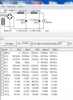
PSUD is normally accurate and 18VAC sounds logical for choke input which always brings a big voltage loss
- Home
- Amplifiers
- Power Supplies
- Reflektor-D builds