Is there a neg Reflektor-D available?
No. We just make symmetric by stacking two positives with their midpoint node taken as virtual zero.
It can be made originally negative by reversing the design and I have done that but the differences between P and N output Mosfets available in TO-220 and also efficient in low voltage levels makes the positive and negative sections more different than I would like for spec.
That's my negative beta schematic for Reflektor in higher voltage output range and it will work with an MTP3055L too (but prefer MTP3055VL or alike for going below 5V). Also that one is a circa 150mA values example so set* at about 0.5A CCS and you can use even more than 5V across it (V1-Vout=M2's VDS) for even better M2's capacitive parasitics and linearity but sink it well, don't push the IRF610 for core temperature. Use all LEDs instead of R6 like in REF-D. Because of the reversal it will still not be exactly the same as the positive version but maybe close enough if you will find it practically so.
*CCS=VbeQ5/R1
*CCS=VbeQ5/R1
Salas, do you have a simple schematic on how to stack two positive supplies to make one negative?
Is it the positive of second and ground of first tied together to make it virtual ground?
Is it the positive of second and ground of first tied together to make it virtual ground?
Hello all 🙂
just to report that the sound has improved during the day... maybe after 8 hours of continuous playing...
more musical and more details..
maybe because the parts are burn in.. i don t know...
just to report that the sound has improved during the day... maybe after 8 hours of continuous playing...
more musical and more details..
maybe because the parts are burn in.. i don t know...
just to share my experience with ps for my dac...(cs4397 with transformers output)
i started with tps7a4700 it was good.. then lt3042( ..better music with more analog sound..( but not so much different)
the now salas reflektor... well.. this is board is miles ahead after some hours of working .. not a little better...
now i understand why many people prefer shunt regulators on dacs..
Hi Salas,
What du you think about this schematic Reflektor D neg. On M1 position MTP3055L. CCS is complementar transistor IRF610 (positiv version use IRF9610) ?
Best regards.
What would be a replacement for 2SK170/LSK170 in that design?
Salas, do you have a simple schematic on how to stack two positive supplies to make one negative?
Is it the positive of second and ground of first tied together to make it virtual ground?
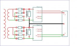
Here again. Its also in the Ref-D pdf build guide. Take notice, two independent secondary and two bridges are an imperative. "G" are sense zeroes. This artwork was drawn by RCruz if I remember correctly.
Attachments

What would be a replacement for 2SK170/LSK170 in that design?
Any low noise NJFET with Vgs (off) less than -2.5V and moderate IDSS. Try a PF5102 maybe that I successfully use in the DCSTB stabilizer/multiplier PSU for my DCG3 preamp.
Hello all 🙂
just to report that the sound has improved during the day... maybe after 8 hours of continuous playing...
more musical and more details..
maybe because the parts are burn in.. i don t know...
Nice. Should be the lytics shaping up. More tunings available for you to test ahead, i.e. errr... stay tuned 😀
Here again. Its also in the Ref-D pdf build guide. Take notice, two independent secondary and two bridges are an imperative. "G" are sense zeroes. This artwork was drawn by RCruz if I remember correctly.
Thanks Salas!
Is there any advantage in using a real negative supply vs two positive supply with virtual ground?
Depends on load circuit's build specifics like how its ground routes are drawn out or how it mixes stages zero points. A midpoint voltage virtual ground can remain easier cleaner than a tending to be polluted real all common returns ground. Uses yet another separate secondary and rectification after all. You can't mix a midpoint voltage "ground" with real zero correlated grounds though. When a DC difference will develop between them, DC current is going to rush. That's why it uses isolation back to having its own transformer secondaries.
Here again. Its also in the Ref-D pdf build guide. Take notice, two independent secondary and two bridges are an imperative. "G" are sense zeroes. This artwork was drawn by RCruz if I remember correctly.
Wouldn't it be that more appropriate ?
Attachments
As I see it, nope.. If you connect it like that, you are not really using the bottom ref-d. Your "negative" rail is unregulated and at way higher voltage than the positive rail.
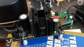
here is another one.... for 3,3v on my hifiberry digi+pro digital side.
just connected now...all stock parts like the first one. Sounds cleaner as the first one...
just connected now...all stock parts like the first one. Sounds cleaner as the first one...
Attachments
Last edited:
As I see it, nope.. If you connect it like that, you are not really using the bottom ref-d. Your "negative" rail is unregulated and at way higher voltage than the positive rail.
Can't see why that should happen, done it with monolithic regulators. I don't know if it gonna pick up noise though.
here is another one.... for 3,3v on my hifiberry digi+pro digital side.
just connected now...all stock parts like the first one. Sounds cleaner as the first one...
Is the fet mod included in this one ?
No fet mod yet... i need to listen for a few days before modsIs the fet mod included in this one ?
Can't see why that should happen, done it with monolithic regulators. I don't know if it gonna pick up noise though.
This is not the same. Chips may have one sense terminal but here there are two. You have shown it sensing at the load but you don't do that for its zero return point also. So first thing is there are sense terminals that you have to short with their respective force terminals in your example. Isn't even working like that.
After having them all closed (two wire mode) its possible you transfer your zero returns node back near to the raw DC area but its dirtier when so close to the reservoirs and even further from the now at output connectors closed sense points. Creating a wider loop area for no benefit in other words. Increasing the possibility for noise pick up as you already said. To picture it better, when current is send down a physical path it wants to follow the closest distance path to it back for returning. Imagine if all that was a ground plane and you had a plus and a minus wire on the other side, the return to zero currents on the copper plane would naturally try to go flow themselves back directly underneath those wires.
Hello!
I conected one of my Ref boards I have since more than 2 years ago, to the Amanero board and I installed a 1ohm resistor in R1.
It significantly improved the sound, as before this Ref board had 2ohm in R1.
I also installed a Jupiter cap in C1, (0,1uF), the best of Jupiter range. It seams crazy and I know that many times better parts do nothing, but this cap improved the sound, adding more fine details and subtle sutff to the music.
What is an issue now, is that the heat sink gets to hot!
What should be done here?
Please help!
Thank you.
- Home
- Amplifiers
- Power Supplies
- Reflektor-D builds