Can you resolve the noise/oscillation frequencies?
Try adjusting the horiz time step all the way up to shortest.
Try adjusting the horiz time step all the way up to shortest.
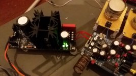
![WP_20170615_003[1].jpg](/community/data/attachments/556/556917-94d4f6974f3c3f2820dc7405a315c9c1.jpg?hash=lNT2l088Py)
If I intend to pull ≈250mA in total from one Reflektor-D supply, could I use a 15VA 9VAC per secondary toroid instead of the recommended 30VA transformer? Or is 30VA utmost necessary?
If the transformer is well made it won't get much hot at 0.25A and it will be alright. The 30VA spec is for covering with ease all the constant current setting scenarios mentioned in the guide.
Can the Reflector D be used to supply 3.3V to one of the DIYinHK USB to I2S boards? The XMOS multichannel one seems to require a max 800 mA and average of 400 mA? I already have one of the kits.
XMOS Multichannel high-quality USB to/from I2S/DSD SPDIF PCB - DIYINHK
XMOS Multichannel high-quality USB to/from I2S/DSD SPDIF PCB - DIYINHK
It can if you will use a 0.68R 3W current setting resistor. Better with a 7.5V transformer to save 3W excess heat on the input MOSFET. The 9V typical Tx recommendation is to include a 5V output range in no more than 600mA setting. You will have 900mA CCS and 3.3V Out.
Would it work to supply this load at 3.3V off of one secondary and a similar 5V load off the other secondary with the 7.5VAC transformer?
It would work but for best performance we prefer to have at least 5V DC across this regulator. If your mains are a bit on the plus side usually and you will use Schottky rectifiers which have lower voltage loss you might get away with 7.5V AC for the 5V set regulator also.
So it looks like there are compromises to using the 9VAC or the 7.5VAC transformer. Which one would work better? I guess it would be better for both the 5V and 3.3V regulated supplies to each have their own transformers, but that seems like overkill.
Using 9V for both is OK for voltage headroom. Because you ask for strong load current, it will bring 7W dissipation to the IRF9610 in the 3.3V section. Better build the REF-D Mini which is using external sinking. To can sink it better and not worry about saving heat through transformers optimization.
Advice needed!
I've 3 Reflector D for powering my Soekris dam1121 board.
Two 5V with CSS 0.3 (R1 – 2 Om) for powering +-5V R2R ladder. Max current consumption – 50mA, typical – 20mA.
One 5V with CSS 0.6 (R1 – 1 Om) for digital line 5V. Мax current consumption – 350mA, typical – 250mA.
All lines have one common ground point in the vicinity of dam1121. 4 wire connection.
All works fine.
But.
While experimenting with different power supply cards, I’ve noticed some strange and quite big spikes at 150 Hz, 250 Hz (see noise spectrum graf from RMAA 6.4.1 measurement software, output from R2R ladder).
They are quite big comparing with LDO TPS7A4700.
Is it my mistake or feature of Reflector D?
Attachments

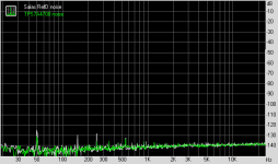
The white peaks are taller than the green by 5 or 6dB at 50Hz and 250Hz. Same height at 550Hz. Those are common between the reg cards compared powering. The 150Hz is alone to the white. The random noise grass is the same between them. Maybe its the measurement limit or the DAC's limit. Those very low level needles are mains frequency harmonics at around -130dB. Must be what is picked up by the voltage output cabling. Or somewhere else in the whole build. If they were residual of the two regs they would have been based on a 100Hz ripple spike. Try two wire mode too in case its the sense loop picking up. Or try shielded coax for the sense and compare to before and two wire mode. Keep the best looking or the best sounding if you can hear any change because those needles are way too low in dB for directly listenable. But they can imply some general little improvement if battled further (doubtful).
Hello, finally i fisnish one Reflektor for 5v.
rr-2ohm
it´s powering my lampucera board.
the sound is very good (only half an hour playing)... no moods only the stock parts with the resistor r6 in place.
i have more boards.. maybe a try another with different parts..
the sound is very powerfull and clean 🙂 very very good
thank all!!! 🙂
rr-2ohm
it´s powering my lampucera board.
the sound is very good (only half an hour playing)... no moods only the stock parts with the resistor r6 in place.
i have more boards.. maybe a try another with different parts..
the sound is very powerfull and clean 🙂 very very good
thank all!!! 🙂
Attachments
Last edited:
Great. Nice to know! Don't forget to try JFET VS R6 mod also to see what you prefer better in your own application among other different parts tests.
Great. Nice to know! Don't forget to try JFET VS R6 mod also to see what you prefer better in your own application among other different parts.
i will do that... just listening for a few days like this...
i was using an double lt3042 from another member... was very good too... but...
i think this is even better... more dynamic and cleaner sound.
I had experience already from TI's lowest noise chip sound when I put together the REF-D. I wouldn't make this one if it had nothing different to offer. Plus you have access to tune it as you like 😉
One question about the wires.
For 2 wire connection i disconnect the sense pins only?
What is the correct gauge?
Tks
For 2 wire connection i disconnect the sense pins only?
What is the correct gauge?
Tks
One question about the wires.
For 2 wire connection i disconnect the sense pins only?
What is the correct gauge?
Tks
You also have to securely short S+ with F+ and 0 with 0 locally at or under the output connector. The shorter the distance to the load the more you can relax the thickness but better don't use less than 1.3mm diameter wires (16 AWG) for 10cm length. That's about 1mΩ contribution. 18 AWG (1mm d) would add about the same mΩ for 5cm length and so on and so forth.
- Home
- Amplifiers
- Power Supplies
- Reflektor-D builds