Hey, its ticking. The more loaded the less heat from the output Mosfet. For output voltage drop don't expect a lot. Can't say how much in your arrangement, depends on heat proximity to the four BJTs mainly. Load it heavier and see.
It does indeed! ...
I loaded it with 8,4ohm (600mA) - Nothing to see except rock solid output 🙂
The mur820 one's will be sinked (with insulation pads) to bottom plate; they do not get that hot, but for long term it's best. And they also was fitted as that for being used as feet for pcb.
I am just in doubt, also regarding the things DimDim wrote here before if this is the right thing to do? -My PI is the B model, and according to some meassurements done on the net, the consumption never goes more than 450-500mA... But the again if it peaks large, will it affect the PI's stability and quality regarding music production? - I dont know yet, but time will ofcause tell. 🙂
I will have to do two more Reflectors now! -Ohh hey, the bare DAC just arrived from HongKong today... 😀
Jesper.
Hey here 😛
First fireup on this shuntreg. was success 🙂
First setup is loaded with 5.04 / 20 ohm = 250mA
The voltage (5.04 VDC) is excatly was the LED's *2 + 1.22 was giving me. I was not thinking, that there was no voltagedrop, but is it right that this voltage will be stable until CCS (0.61/0.56=~1000mA) is reached ?
I will find another resistor, and try to load the reg. a little more now.
But! --- It is getting hotBut with some good sinks, it will be doable i think; my transformer is delivering 12vac, which does not make things better.
Anyway i now know that my pcb is working, just wishing i had a scope right now 😱
Jesper.
You can lower the temperature of your mosfet by lowering DC in.
To do so you must lower your AC in and increase main reservoir capacitance at the same time.
Refer to post 815 in this thread for calculations to find best balance between AC in and main capacitance for 1A output.
http://www.diyaudio.com/forums/power-supplies/261031-reflektor-d-builds-82.html#post4818424
Thanks a lot man 🙂
I use 15000uF/25v on my rectiver board (Part of RefD-board - can be seperated) ... Those values is not far from, what you and Salas calculated in those post's 🙂
Jesper.
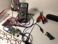
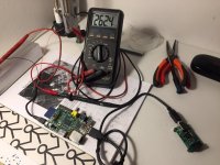
More test's...
I could not resist trying a PI with the Reg. -And good thing is, i figured out excatly how much the Xmos usb to i2s use. (~120mA)
Well i don't know how precise my DMM is, in the mA state, but 120mA sounds pretty good/normal for me.
Jesper.
I could not resist trying a PI with the Reg. -And good thing is, i figured out excatly how much the Xmos usb to i2s use. (~120mA)
Well i don't know how precise my DMM is, in the mA state, but 120mA sounds pretty good/normal for me.
Jesper.
Attachments
More test's...
I could not resist trying a PI with the Reg. -And good thing is, i figured out excatly how much the Xmos usb to i2s use. (~120mA)
Well i don't know how precise my DMM is, in the mA state, but 120mA sounds pretty good/normal for me.
Jesper.
Pi has pretty nasty and noisy usb port. Additionally in the pi model you have usb share bus with LAN. Pi also has jittery I2S signal without MLCK. Moreover from what I see your xmos model is the old one with low processing power compering to new xmos216.
In your case I would skip usb and xmos and use Hifiberry Digi+ Pro hat instead. It delivers MLCK (from two onboard audio clocks) to pi to generate bitclock and treat pi as slave in this regard. In return you get very very low jitter I2S signal (with MLCK) straight from hifiberry hat with which you can furtherly feed your AD1856 R2R directly.
First off here, thanks for all that acknowledge; i did not see a new pihat with clocks and i2s out before 🙂 -Sure i have been studing that today.
Anyway i need (for now) the xmos, witch will be externally feeded by one of my Reflector-D's... trick is to remove a little SMD resistor/fuse/cap. whatever on the pcb. https://hifiduino.wordpress.com/2013/04/16/got-the-xmos-384khz-usb-interface/; Case is that i would like to try the Tidal Masters https://support.tidal.com/hc/en-us/articles/115000397069-TIDAL-MASTERS; and for now only solution is with desktop application connected to an USB Dac.
Regarding the clock, i have not been studying this much right now, but i think that DAC will use the clock's on the USB to I2S interface ?
I think that supplying external power to the USB interface, i will get rid of most of the noise from the PI?
Back to work then 🙂
Jesper.
The thing to remove from your xmos pcb to power it externally is ferrite bead.
If your AD1856 is from diyinhk the yes it will accept I2S from xmos or from Hifiberry digi+ pro.
Applying reflector to your xmos will of course decrease the noise from Pi. However from my experience with hifiberry digi+ pro it works much better. Try both yourself 🙂
@lykkedk
As far as Tidal masters it is MQA coded. Your ad1856 will not decode that natively.
So, in your case whole MQA decoding to PCM will be done in your PC and then PCM will be send to your DAC through USB. So MQA will only add additional processing to your PC, nothing else. Additionally since it is lossy compression it will be less precise as flac (hires streaming in tidal).
This whole MQA ******** hype was just invented by audio industry to make more money.
Few links to read on that:
https://www.sempre-audio.at/HIGHRESAUDIO_stellt_Angebot_an_MQA_Daten_ein.id.5543.htm
Schiit Audio, Headphone amps and DACs made in USA.
@lykkedk
As far as Tidal masters it is MQA coded. Your ad1856 will not decode that natively.
So, in your case whole MQA decoding to PCM will be done in your PC and then PCM will be send to your DAC through USB. So MQA will only add additional processing to your PC, nothing else. Additionally since it is lossy compression it will be less precise as flac (hires streaming in tidal).
This whole MQA ******** hype was just invented by audio industry to make more money.
Few links to read on that:
https://www.sempre-audio.at/HIGHRESAUDIO_stellt_Angebot_an_MQA_Daten_ein.id.5543.htm
Schiit Audio, Headphone amps and DACs made in USA.
You are proberly right 🙂 ... And ehh i think i better stop, before going to off-topic here
 ...
... I read also about the MQA, and what it does. When "unfolding" MQA on pc, its "unfolded" to 24/96... If one had a capable dac (i do not) it will be "unfolded" into 24/192 as far as i know. Anyway i think it would be fun to hear the difference (if any); I (Us here at home) allready tried comparing AB through spotyfi/tidal, and that was pretty easy to hear btw...
Thanks for the comments btw.
Jesper.
Sure. Lets stop it here then. Just do not forget that you can also upsample your tidal hi-res into 24/192 or higher or even convert it into DSD (in case of delta sigma chips)You are proberly right 🙂 ... And ehh i think i better stop, before going to off-topic here
I read also about the MQA, and what it does. When "unfolding" MQA on pc, its "unfolded" to 24/96... If one had a capable dac (i do not) it will be "unfolded" into 24/192 as far as i know. Anyway i think it would be fun to hear the difference (if any); I (Us here at home) allready tried comparing AB through spotyfi/tidal, and that was pretty easy to hear btw...
Thanks for the comments btw.
Jesper.
Salas, please help me answer, I received a question concerning Reflektor-D power supply:
...and noise or PSRR numbers? Like AMB provides for the Sigma 11 and 22.
...and noise or PSRR numbers? Like AMB provides for the Sigma 11 and 22.
Ok. thanks att., I shared your wonderful module on a equally interesting discussion thread:
Beguinning:
[wiki=https://www.usaudiomart.com/forum/viewtopic.php?f=35&t=1172 ]%[/wiki]
My last post there, scroll down, till reaching Ref-D pics:
[wiki=https://www.usaudiomart.com/forum/viewtopic.php?f=35&t=1172&start=1440]%[/wiki]
Amazing a lot of discusion around power supplies for digital USB modules, and nobody never talks about Ref-D!
Nice that you spread your experiences. I avoid to claim numbers out of simulations. Just keep in mind that this reg has a unity gain well filtered Vref (i.e. all the voltage is already there, not multiplied by a gain circuit) so it is inherently low noise. Also post#156 can give some FFT indications from one certain combo.
Thanks letting me share, please forgive me I must ask in advance.
On my last Ref-D build (12,8v supply for Class T chip amp) Ref-D has outperformed Bib light years ahead.
New additions are a second Mundorf (CM-6800uF) as seen in pic and a selenium diode bridge.
Resistor R1 is in series= Caddock MP 2R2 + 3R wirewound pot.
After adjustement while music playing, I set 4R9.
Pretty low power for a whole integrated amplifier! But further only to 4R8 is enough to downgrade the performance.
Attachments

Hi, Salas,
Since there might be voltage drift after some use (there was a report some posts back), is it wise to use socket pins for J2 and LEDs (that way, replacement is made easy)? Any downside for this practice? I suppose the use of socket pins only increase local resistance and maybe capacitance between leads a tiny little bit (negligible I guess). Thanks.
WYAN
You may keep the socket type pins for long enough until sure for voltages in the final installation environment. So to can try quick alternatives there. Better solder after that to secure against metal corrosion of the LEDs & Jfet pins. If not directly to pads, maybe on the socket itself not to disassemble the whole thing from a chassis for just a minor rework.
Hi, Salas, thanks. I was talking about voltage drift after maybe a few months. I do understand that a few hours is needed for the voltage to settle initially. However, there was a report that voltage could shift after a long while of use (a few months). If this ever happens, replacing the leds/j2 could be a real pain once everything is soldered.
I don't know what would make a change after few months in a same thermal environment. Maybe some weird physics in the Leds that I am surely not an expert to know if existing at all. Or ambient temperature drastic changes? I haven't seen drifts larger than tenths of Volt and those were thermal settling of the whole board parts related. In any case few months are not crucial for pins corrosion and you may extend the non soldered period that much to can easily measure and adjust your build again.
Thanks letting me share, please forgive me I must ask in advance.
On my last Ref-D build (12,8v supply for Class T chip amp) Ref-D has outperformed Bib light years ahead.
New additions are a second Mundorf (CM-6800uF) as seen in pic and a selenium diode bridge.
Resistor R1 is in series= Caddock MP 2R2 + 3R wirewound pot.
After adjustement while music playing, I set 4R9.
Pretty low power for a whole integrated amplifier! But further only to 4R8 is enough to downgrade the performance.
Can't say without numbers. Like standing consumption VS max consumption of the amp.
- Home
- Amplifiers
- Power Supplies
- Reflektor-D builds