YEs output is via Mosfets ,i use 2SK215 *was unable to find 216 in here . Using this DAC via PCM2706 . Both are with normal temp , PCM is tested via DIG Out .On the output of the TDA i got -4,56 V *to gnd and 2,33 V to gnd again ?
YEs output is via Mosfets ,i use 2SK215 *was unable to find 216 in here . Using this DAC via PCM2706 . Both are with normal temp , PCM is tested via DIG Out .On the output of the TDA i got -4,56 V *to gnd and 2,33 V to gnd again ?
I couldn't give any recommendations, if you use different parts in the circuit.
Please ask in ecdesigns thread, if you could use the 2SK215 and report back!

I think that the only difference between those two mosfets (2SK215 and 2SK216) is Vds rating, 180V vs 200V, I think there is no problem with that.
As oliver says there was a small problem with the V3.0 board where you must do a leg change in order for the output stage to work properly. By the way:
¿And what do you have on the RCA connectors? ¿Have you adjusted the pots of the buffer to 0 volts?
As oliver says there was a small problem with the V3.0 board where you must do a leg change in order for the output stage to work properly. By the way:
Krokotam_ said:On the output of the TDA i got -4,56 V *to gnd and 2,33 V to gnd again ?
¿And what do you have on the RCA connectors? ¿Have you adjusted the pots of the buffer to 0 volts?
I think that the only difference between those two mosfets (2SK215 and 2SK216) is Vds rating, 180V vs 200V, I think there is no problem with that.
As oliver says there was a small problem with the V3.0 board where you must do a leg change in order for the output stage to work properly. By the way:
¿And what do you have on the RCA connectors? ¿Have you adjusted the pots of the buffer to 0 volts?
You are absolutely right only VDS is different! But i have done the pin swap ... , the interesting thing is that +5 v on pots change in small range from 4.93 v to let say 4,75 v , even less . The output remains quiet as hell .
You are absolutely right only VDS is different! But i have done the pin swap ... , the interesting thing is that +5 v on pots change in small range from 4.93 v to let say 4,75 v , even less . The output remains quiet as hell .
You have failure on both R I/V resistors!
The input is the square point. You soldered the resistors to both round points... 😉
Please correct this and report back.
Guys thank you for helping me ! So i have corrected the I/V resistors and tune up the measurement points so the voltage there is 0.00 V , but still nothing on the output , complete silence *only turn on noise and turn off . On Right RCA i have -0.05 v DC on the other 0.00 v . I have checked anyway i2s on DATA IN - 0,65 V , FS - 0,71 V AND DATA 0.09 V all to GND.
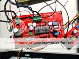
recent build
http://i187.photobucket.com/albums/x124/krokotam_/TDA 1541 R1/P8050008_zps5bfc6a3e.jpg

recent build
http://i187.photobucket.com/albums/x124/krokotam_/TDA 1541 R1/P8050008_zps5bfc6a3e.jpg
Last edited:
Guys thank you for helping me ! So i have corrected the I/V resistors and tune up the measurement points so the voltage there is 0.00 V , but still nothing on the output , complete silence *only turn on noise and turn off . On Right RCA i have -0.05 v DC on the other 0.00 v . I have checked anyway i2s on DATA IN - 0,65 V , FS - 0,71 V AND DATA 0.09 V all to GND.
recent build
http://i187.photobucket.com/albums/x124/krokotam_/TDA 1541 R1/P8050008_zps5bfc6a3e.jpg
Your PCM2706 Kit from analog metric is powered from 3.3V. The I2S attenuator on the V3.0 is build for 5V signals. So we have two possibilities:
1st - you insert my UHS-Buffer module
2nd - you do the 3.3V I2S attenuator modification (recommended)
Thank you for your support Oliver , based on your last suggestions i have made this project up and running * a BIG thanks from me ! Well everything fine but not at all 🙂 There is a strange noise in both channels *it increases when there is no sound, i guess something to be done with the output [I`m going tomorrow to move those knobs - pots ] Should i shorter the I2S cable length ? Again thank you for your time you have some nice beers from me if you plan a holiday near Black Sea 😉
Thank you for your support Oliver , based on your last suggestions i have made this project up and running * a BIG thanks from me ! Well everything fine but not at all 🙂 There is a strange noise in both channels *it increases when there is no sound, i guess something to be done with the output [I`m going tomorrow to move those knobs - pots ] Should i shorter the I2S cable length ? Again thank you for your time you have some nice beers from me if you plan a holiday near Black Sea 😉
¿Did you make Oliver`s suggested 2nd option? If the noise is down the music level it can be i/v circuits fault (¿gnd loop?), if the noise is louder than music when playing then it can be some bck related issue.
I have made the second option - moding the board to 3.3 v I2s . Just to check today Dc Refference module I believe that there are some trimming that might help this noise , it is on the background of the music not that notable when playing music but it increases when music stops 
it seems that it might be a grounding loops ...
it seems that it might be a grounding loops ...
Last edited:
Thank you for your support Oliver , based on your last suggestions i have made this project up and running * a BIG thanks from me ! Well everything fine but not at all 🙂 There is a strange noise in both channels *it increases when there is no sound, i guess something to be done with the output [I`m going tomorrow to move those knobs - pots ] Should i shorter the I2S cable length ? Again thank you for your time you have some nice beers from me if you plan a holiday near Black Sea 😉
Hmm... Did you change the input voltage to 3.3V?
You should do also the 2nd recommended modification! The free running DEM oscillator sound´s better 😉
If you haven´t a SMD cap, use a small film cap on the backside of the Red Baron.
Last edited:
I think i`ve got it 😎 Voltage on the clock ! is dropping maybe my 3.3 CZ 100 mA voltage regulator is not enough for here ...
Probably way off-topic but has anyone else tried a TDA1541 chip (NOT the 1541A) in one of Oliver's PCBs?
I have one that has sat in a drawer for 30-odd years, ever since I swapped it for a 1541A in my then-current CD player in about 1986 or '87. I recently fitted it in one of Oliver's green (pre-Red Baron) PCBs - it worked straight away, no mods needed, and sounds very, very good.
I've not had a chance to do detailed comparisons with the "newer" chip but I've lived with it for a week now and am still greatly liking the sound.
Moral: if you have a 1541, dig it out and put it to work.
Sorry, I've got to ask again.
But where did you get that connector for the psu to the dac?
How many pins are you actually using ? 6 or 7?
But where did you get that connector for the psu to the dac?
How many pins are you actually using ? 6 or 7?
6 pins = 1 connector 4 pins +1 connector 2 pins ( 4 pins TDA power supp 2 pins oscillator power supp )
Hmm i have not edit option for my previous post ...
I have made the first modification for this DAC clock , but you have suggested to do the DEM clock , hmm . There are a few things i don`t understand .
Should i keep the first modification diodes and changes to do the second ? Or in main what is going on with the 3.3 K resistor , 100 R resistors ,68 R they where changed with diodes and bridge ? Should i keep them or just leave their place blank ?
image hosting more than 5mb
I have made the first modification for this DAC clock , but you have suggested to do the DEM clock , hmm . There are a few things i don`t understand .
Should i keep the first modification diodes and changes to do the second ? Or in main what is going on with the 3.3 K resistor , 100 R resistors ,68 R they where changed with diodes and bridge ? Should i keep them or just leave their place blank ?
An externally hosted image should be here but it was not working when we last tested it.
image hosting more than 5mb
Hmm i have not edit option for my previous post ...
I have made the first modification for this DAC clock , but you have suggested to do the DEM clock , hmm . There are a few things i don`t understand .
Should i keep the first modification diodes and changes to do the second ? Or in main what is going on with the 3.3 K resistor , 100 R resistors ,68 R they where changed with diodes and bridge ? Should i keep them or just leave their place blank ?
An externally hosted image should be here but it was not working when we last tested it.
image hosting more than 5mb
The modifications are independend from each other.
Look in the attached pdf from the Red Baron V5.0. It´s easier to understand 😉
Attachments
Sorry for flooding your thread 😱
But i have done your last suggestion :http://img24.imageshack.us/img24/1070/redbaronfreerunningdemo.jpg : free Dem oscillator mod , aaand there is no sound again 😱 . Based on the 2 previous modifications i have put a bridge on 100R resistors , 2 diodes on 3k3 resistors , replaced 1k resistors with diode strings 3k3 , replaced 2k2 with 6k8 , removed 12k , removed signal diodes and 74HC02 . No sound at the output maybe i have done some mistakes can you correct me please ? Are you sure that this DEM clock is compatible with analogmetric I2S ?
But i have done your last suggestion :http://img24.imageshack.us/img24/1070/redbaronfreerunningdemo.jpg : free Dem oscillator mod , aaand there is no sound again 😱 . Based on the 2 previous modifications i have put a bridge on 100R resistors , 2 diodes on 3k3 resistors , replaced 1k resistors with diode strings 3k3 , replaced 2k2 with 6k8 , removed 12k , removed signal diodes and 74HC02 . No sound at the output maybe i have done some mistakes can you correct me please ? Are you sure that this DEM clock is compatible with analogmetric I2S ?
Please ignore my last post . Grounds - very important for RUNNING THIS CLOCK . Everyone who is going to use it connect your I2S device ground to DAC GROUND , otherwise you bang your head and thing what is wrong ... I also recommend this DEM clock : First Impressions : Sound is very relaxed mids are clear and highs are a bit mild . Congratulations Oliver very well done !
Cheers
Ivan
Cheers
Ivan
- Status
- Not open for further replies.
- Home
- Group Buys
- "Reference" TDA1541A DAC with I2S-BUS architecture