Triode_Al
Do you have any experience with the topology of the Hammond 229 series?
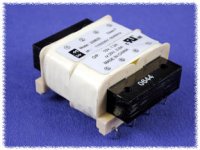
Not really but it looks very good; with the split bobbins (2x primary 110V; 2x secondary) that leads to low coupling.
Alternatively there are some nice R-core transformers of 2x18V on the market. For instance at sellers that also sell the EES dac.
I surely recommend one of these.
I have one of those Hammond Transformers, they are quite good but they can have a bit of mechanical hum.
Salas Shunt for WaveIO?
I see Oliver you also use WaveIO. I currently have mine powered from linear supply (choke and about 30ku filter) but very average 5V reg. As you know, it draws about 380ma and spec'd for 500ma. Will your 5v Salas Shunt deliver this much current? Does it make improvement to justify another Salas?
I see Oliver you also use WaveIO. I currently have mine powered from linear supply (choke and about 30ku filter) but very average 5V reg. As you know, it draws about 380ma and spec'd for 500ma. Will your 5v Salas Shunt deliver this much current? Does it make improvement to justify another Salas?
I have one of those Hammond Transformers, they are quite good but they can have a bit of mechanical hum.
Thanks ZUM911. You are right on that point. I had one in a Peter Daniel 1543 NOS DAC and it did have a mechanical buzz. I am actually thinking of using his board to power the WaveIO and the Alix PC board. I have a few of these 229 tx's that I picked up cheap in surplus. I think I'll use them for the first flight for the 1541a supplies. I'll mount them in some silicone to isolate the vibration. I will reserve the R core as a possible future upgrade. I also have some Hammond transformers for the Lampizator B+ that seem to have a little mechanical buzz. Seems to be Hammond Achilles heel.
I have one of those Hammond Transformers, they are quite good but they can have a bit of mechanical hum.
It is evident they will hum, if there is an unequal current through the positive and negative rail. Then the two separate winding coils get unequal loading each half cycle: there then is mechanical noise.
- It is best to use a shunt : give both positive and negative a current source of 200 mA and then even when the positive side of the TDA1541 draws less than the negative side there will be no hum.
Great insight. I will use the Salas shunts set to 200ma. In this application they may do very well. The low profile also fits the case design.triode_al said:[*]It is best to use a shunt : give both positive and negative a current source of 200 mA and then even when the positive side of the TDA1541 draws less than the negative side there will be no hum.
[/LIST]
a quick question regarding the RB dac. I'm finally almost finished assembling and wiring the boards and hope to launch the dac very soon 🙂
For DDNF output stage I use the following shunt and due to the circuit I'm limited in specific voltages. For +-19v it's fine, I've got ~18.9 after half on an hour, but for 15v line there are two options - either to have 15.8v (due to 15v zener) or use 13v zener and get about 13.8 voltage... What would be preferable here? Perhaps later I would swap the regs with Salas versions, though for now the main goal to finalize the project 🙂
For DDNF output stage I use the following shunt and due to the circuit I'm limited in specific voltages. For +-19v it's fine, I've got ~18.9 after half on an hour, but for 15v line there are two options - either to have 15.8v (due to 15v zener) or use 13v zener and get about 13.8 voltage... What would be preferable here? Perhaps later I would swap the regs with Salas versions, though for now the main goal to finalize the project 🙂
a quick question regarding the RB dac. I'm finally almost finished assembling and wiring the boards and hope to launch the dac very soon 🙂
For DDNF output stage I use the following shunt and due to the circuit I'm limited in specific voltages. For +-19v it's fine, I've got ~18.9 after half on an hour, but for 15v line there are two options - either to have 15.8v (due to 15v zener) or use 13v zener and get about 13.8 voltage... What would be preferable here? Perhaps later I would swap the regs with Salas versions, though for now the main goal to finalize the project 🙂
Go with 15.8V. That´s nearest to the recommended voltage. 😉
Bargain Sale
Here you could order two of my ready build Red Baron V4.0 DAC test modules,
witch includes the new 3.3V I2S attenuator and free running DEM oscillator modification.
Also on board is the Tube-I-zator bandwidth limiting modification.
Main Parts
- DEM decoupling with Cornell Dubilier Stacked Metallized Film Capacitors 1µF/16V FCA 1210 caps
- PRP resistors
- Nichicon FPCAP R7 series capacitors
for the special price of
$55 each
including
Worldwide shipping and paypal fee
An externally hosted image should be here but it was not working when we last tested it.
Both sold!
hello again,
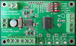
a question most likely to Oliver or anybody who's used twistedpearaudio's spdif receiver.
I'm unable to find the tristate dip switch and according to the manual and Oliver's post here it should have AIF/MS turned on.
Frankly speaking I didn't get the idea how the damn switch works from the manual. Could anyone please assist, should it be wired as on the pic below?
Attachments
Layout
I'm thinking I'll but all the digital stuff in a box...
ie transformers, 2x psu and the regulators
Then use a military type connector to connect these voltages to another box which would house just the red baron dac itself, and the tube stage (with it's own analogue PSU).
Some how I'd have to ground both sides, and power up both sides.
Would this cause a problem?
Good source for Jfet 2SK170BL
Anyone needing the 2SK170? Ebay pak arrived this week. Happy to report that assembled Salas shunts. They worked perfectly right off.
My source for the Jfets appears to be reliable.
2SK170 BL Original Toshiba FET N CH K170 2SK170BL x 8 | eBay
Now no excuses. All parts in hand. Need to build a chassis for this beast! Thanks Oliver for making this part easy. 😉
hello again,
a question most likely to Oliver or anybody who's used twistedpearaudio's spdif receiver.
I'm unable to find the tristate dip switch and according to the manual and Oliver's post here it should have AIF/MS turned on.
Frankly speaking I didn't get the idea how the damn switch works from the manual. Could anyone please assist, should it be wired as on the pic below?
The DIP switch config on your photo is correct. Witch Red Baron version did you have?

The DIP switch config on your photo is correct. Witch Red Baron version did you have?
thanks! It's v3.0 configured to 3.3v and almost ready now, just need to solder the pins of spdif receiver and add 4 i2s lines.
Just curious, if I wanted to use an external usb i2s transport (and swap it out) would that be possible?
Just curious, if I wanted to use an external usb i2s transport (and swap it out) would that be possible?
Not sure I am understanding your question, but I use a WaveIO card as the 'external' USB>I2S converter. Works very well with TDA1541A. Swapping is as easy as disconnecting the I2S cables and putting in a different source of I2S signal.
- Status
- Not open for further replies.
- Home
- Group Buys
- "Reference" TDA1541A DAC with I2S-BUS architecture