Hey, just got my matched jfets and my tda1541a chips.
Hmm, the shunt regulators have 3x spots for the 170's. Where would I use my matched pairs, or does it matter?
Hmm, the shunt regulators have 3x spots for the 170's. Where would I use my matched pairs, or does it matter?
Hi regal,
Keep in mind that my design is primarily a non SMD design!
The the decoupling caps trace length is 6.4mm max. with a resistance of 4mOhm. However, with a pure SMD design you could save the 4mOhm, but is this still audible... 🙄
With this real short trace length it sounds fantastic, especially with John´s recommended SMD caps.
An externally hosted image should be here but it was not working when we last tested it.
As you could see on the photo, the ground plane is complete uninterrupted on the top layer. Compare the differences between V3.0 and V4.0 in my blog.

Hello Oliver, I see you are still using 2xTDA1541A in parallel, ¿Do you notice positive results from paralleling? I ask you this because I have also been using 2xTDA1541A until now but from the latest changes John suggested (Free running DEM oscillator, changes on the attenuators...) I decided to use only one and the improvement is big in comparison with The Red Baron V3.0 circuitery, I suppose those big improvements come from the changes in the circuit, but I am starting to think there is really no benefit on sound quality when paralleling. I think ThorstenL and John also think this way
 , no long ago John said that when paralleling chips Jitter goes up: http://www.diyaudio.com/forums/digital-line-level/79452-building-ultimate-nos-dac-using-tda1541a-459.html#post3233523
By the way, the latest changes are highly recommended, it sounds incredible 😉.
Greetings 😉,
Oier.
Excellent,Hey, I picked up a couple of tda1541 chips too.
Which tubes are in your lampizator output stage?
I use 6np2. Tried 6np1 but for my taste no comparison to 6np2.
I second that. I used a lesser converter. WaveIO kicks it up and shows what tda1541a is capable of. Then you build a dedicated power supply for WaveIO and you'll never go back. So even in its basic form, WaveIO is still not bringing enough. No end of tweaks to make to the PC/OS and still the TDA1541a just breaths new life into the music. Even the USB cable has a significant effect. (short as possible and solid core wire).The WaveIO works superbly with the TDA1541A, esp with a good PSU. Highly recommended.
In my target layout, the PC processor, WaveIO and Red Baron will be arranged in 3d to allow shortest possible USB and I2S connections.
Last edited:
Even the USB cable has a significant effect.
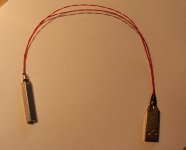
Best DIY USB cable I've come across so far uses 30AWG Kynar wire-wrap wire - sonically as good IMHO as Cat5 solid core but, being flexible, less likely to damage connectors.
See pic - note that one of the pairs is D+/D-, the other is a doubled-up Gnd lead; there's no need for V+ with the WaveIO. (I didn't bother with a screen as the lead is so short. That, of course, minimises capacitance but I did it that way because, essentially, I'm lazy.)
Attachments
I've got the following transistors;
bc550cbu x2
bc560cta x2
I know they're pretty close to what's on the bom. Are these good for the shunts?
Ok, looks like the other's are obsolete.
bc550cbu x2
bc560cta x2
I know they're pretty close to what's on the bom. Are these good for the shunts?
Ok, looks like the other's are obsolete.
Last edited:
There are 2x .1uf left off the BOM for each shunt.
I think I have spares. Still require these in the shunts right?
I think I have spares. Still require these in the shunts right?
I've got the following transistors;
bc550cbu x2
bc560cta x2
I know they're pretty close to what's on the bom. Are these good for the shunts?
Ok, looks like the other's are obsolete.
You could use them for sure!
There are 2x .1uf left off the BOM for each shunt.
I think I have spares. Still require these in the shunts right?
Salas recommend to skip these two 0.1µF. That´s the reason why they aren´t in the BOM. 😉
Almost done with my PSU. Just need to order some more caps.
I haven't touched the high voltage 150+ v for the tube stage. What have you done with your high voltage section? I'd like to figure out what I need for this and maybe stick it in with the low voltage stuff.
If I can get a hold of your drawings for the case that would be great too.
I haven't touched the high voltage 150+ v for the tube stage. What have you done with your high voltage section? I'd like to figure out what I need for this and maybe stick it in with the low voltage stuff.
If I can get a hold of your drawings for the case that would be great too.
Best DIY USB cable I've come across so far uses 30AWG Kynar wire-wrap wire - sonically as good IMHO as Cat5 solid core but, being flexible, less likely to damage connectors.

See pic - note that one of the pairs is D+/D-, the other is a doubled-up Gnd lead; there's no need for V+ with the WaveIO. (I didn't bother with a screen as the lead is so short. That, of course, minimises capacitance but I did it that way because, essentially, I'm lazy.)
Nice!
Where did you get the connectors?
If possible, even shorter is even better.
I haven't touched the high voltage 150+ v for the tube stage. What have you done with your high voltage section? I'd like to figure out what I need for this and maybe stick it in with the low voltage stuff.
If I can get a hold of your drawings for the case that would be great too.
Because i use a SSHV per channel and a tube rectifier for the B+, you don´t see a populated HV section on my photo´s 😉
Witch drawings did you like to have?
I'd like to get your case diagrams. Hopefully everything will fit... and how you wired that connector up (that would be handy).
I might just be using an unregulated PSU for my tube stage.
I might just be using an unregulated PSU for my tube stage.
Nice!
Where did you get the connectors?
If possible, even shorter is even better.
Ebay!
I got a nice 17" x 11" hammond walnut case. Not sure if I should use it for the dac or the PSU.
How big is that case for your power supply?
How big is that case for your power supply?
Hello Oliver ,
maybe is something stupid i can`t figure at the moment but i need your help 🙂
I have connected all wires but nothing came , as far as I can touch every voltage is OK . Kind of wired but even 5 V is around 4,53 V .
http://postimg.org/image/7e8w28933/
My first suggestions are i/v outputs because i really hate to deal with them , can you please specify how to check output voltage ?
Another thing it seems that AOL and AOR differ ? one is 0.55 V other is around -7 v ?
maybe is something stupid i can`t figure at the moment but i need your help 🙂
I have connected all wires but nothing came , as far as I can touch every voltage is OK . Kind of wired but even 5 V is around 4,53 V .
An externally hosted image should be here but it was not working when we last tested it.
http://postimg.org/image/7e8w28933/
My first suggestions are i/v outputs because i really hate to deal with them , can you please specify how to check output voltage ?
An externally hosted image should be here but it was not working when we last tested it.
Another thing it seems that AOL and AOR differ ? one is 0.55 V other is around -7 v ?
Last edited:
Hello Oliver ,
maybe is something stupid i can`t figure at the moment but i need your help 🙂
I have connected all wires but nothing came , as far as I can touch every voltage is OK . Kind of wired but even 5 V is around 4,53 V .
An externally hosted image should be here but it was not working when we last tested it.
View image: dac2
My first suggestions are i/v outputs because i really hate to deal with them , can you please specify how to check output voltage ?
An externally hosted image should be here but it was not working when we last tested it.
Another thing it seems that AOL and AOR differ ? one is 0.55 V other is around -7 v ?
Hi,
atm i am in holiday, so it's a bit complicated to say.
Did you do the MOS-Fet mod. for the V3.0?
http://www.diyaudio.com/forums/grou...-dac-i2s-bus-architecture-77.html#post2678417
Best,
Oliver
- Status
- Not open for further replies.
- Home
- Group Buys
- "Reference" TDA1541A DAC with I2S-BUS architecture