matched quads
these look ok?
Genuine Toshiba 2SK170BL 2SK170 JFET Transistor N Channel Quad Match | eBay
these look ok?
Genuine Toshiba 2SK170BL 2SK170 JFET Transistor N Channel Quad Match | eBay
I ordered from this source in the past. No problems!
http://www.ebay.com/itm/4x-Toshiba-...522?pt=LH_DefaultDomain_0&hash=item4d0d70e60a

Last edited:

I've contacted them, no reply yet.
Oh, I just ordered the jfets... quads in matched pairs. That should be ok, right?
Matched are not necessary, but ok... 😉
The new Red Baron DAC Module V5.0
The evolution brings the following changes
- Jumper for I2S / simultaneous mode
- latest 3.3V attenuator for I2S & simultaneous mode (by -ecdesigns-)
- free running DEM oscillator (by -ecdesigns-)
- additional U.FL pads for I2S & simultaneous mode
- Separate U.FL-GND route to Digital-GND
Still on the module
- Separate I2S-GND route to Digital-GND
- Separate Analog Output GND route
- Separate GND route for active divider decoupling caps to Analog-GND
- Modified active divider decoupling pads for better SMD 1210 caps soldering
- Un-interrupted ground plane
- Direct shunt voltage inputs with shortest onboard traces
- I2S In-/Outputs with shortest onboard traces
- Onboard Grounded-Gate MOSFET Current Buffer I/V Stage
(-ecdesigns- MK7 version)
- Separate GND-Trace for I2S / simultaneous mode attenuator
- Master/Slave connectors for parallel DAC module usage and external I/V Buffer stages e.g. Tube-I-zator & DDNF Stage
- no SMD Design
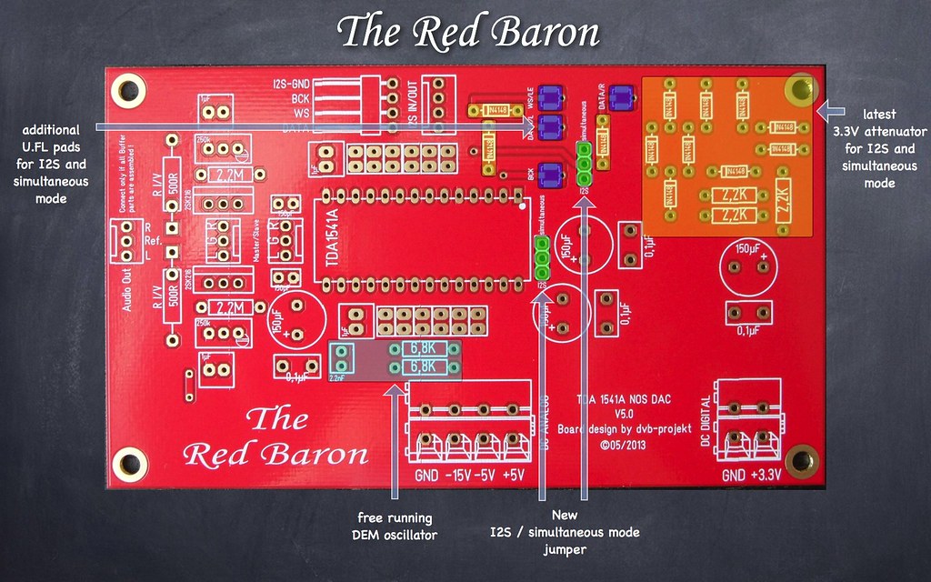
The PCB has the following data:
Material: FR4 - 2mm
Layers: 2
Board size: 125x73 mm
Surface finish: Immersion Gold
Copper weight: 35µm
Soldermask: Both sides - red
Silkscreen: Legend on top
In Stock
The price will be as followed:
Professional 2-Layer PCB: $15
Worldwide shipping: $ 9
Europe shipping: $ 5
paypal fee: 3,9%
Shipping insurance on buyers request!
A donation of $3 USD to diyAudio will be done for every pcb sold.
The DAC module V2.3 will still be available for those,
who want to use it without the TDA1541A Shunt module!
If you want to use the onboard Grounded-Gate MOSFET Current Buffer I/V Stage,
you need additionally the DC-Reference Module
Description
Because the Grounded-Gate Buffer is connected between the DAC output and the passive I/V resistor,
normally the I/V resistor is connected between the DAC output and GND,
you must get rid off the approx. 4V DC on each I/V resistor.
Therefore we must get a new reference GND for each channel.
The circuit is connected to the ref.+5V at the output of the buffer and GND,
with a decoupling cap for each channel.
By trimming each voltage so it exactly matches DC voltage on the I/V resistor,
the DC voltage between I/V resistor and reference becomes zero.
In other words, the DC component is removed without using a coupling cap.
Material: FR4 - 2mm
Layers: 2
Board size: 54x34 mm
Surface finish: Immersion Gold
Copper weight: 35µm
Soldermask: Both sides - red
Silkscreen: Legend on top
Following parts are needed:
2* 2-Way vertical header; 5mm pitch - Mouser Part No.: 571-2828362
2* 470µF/min. 10V decoupling cap - Mouser Part No.: 647-RR71A471MDN1
2* 1K0 multiturn trimmer - Mouser Part No.: 652-3006P-1-102-LF
In Stock
The price for it is $9
Worldwide shipping: $ 4
paypal fee: 3,9%
Shipping insurance on buyers request!
The new Red Baron
V5.0
V5.0
An externally hosted image should be here but it was not working when we last tested it.
The evolution brings the following changes
- Jumper for I2S / simultaneous mode
- latest 3.3V attenuator for I2S & simultaneous mode (by -ecdesigns-)
- free running DEM oscillator (by -ecdesigns-)
- additional U.FL pads for I2S & simultaneous mode
- Separate U.FL-GND route to Digital-GND
Still on the module
- Separate I2S-GND route to Digital-GND
- Separate Analog Output GND route
- Separate GND route for active divider decoupling caps to Analog-GND
- Modified active divider decoupling pads for better SMD 1210 caps soldering
- Un-interrupted ground plane
- Direct shunt voltage inputs with shortest onboard traces
- I2S In-/Outputs with shortest onboard traces
- Onboard Grounded-Gate MOSFET Current Buffer I/V Stage
(-ecdesigns- MK7 version)
- Separate GND-Trace for I2S / simultaneous mode attenuator
- Master/Slave connectors for parallel DAC module usage and external I/V Buffer stages e.g. Tube-I-zator & DDNF Stage
- no SMD Design
The PCB has the following data:
Material: FR4 - 2mm
Layers: 2
Board size: 125x73 mm
Surface finish: Immersion Gold
Copper weight: 35µm
Soldermask: Both sides - red
Silkscreen: Legend on top
In Stock
The price will be as followed:
Professional 2-Layer PCB: $15
Worldwide shipping: $ 9
Europe shipping: $ 5
paypal fee: 3,9%
Shipping insurance on buyers request!
A donation of $3 USD to diyAudio will be done for every pcb sold.
The DAC module V2.3 will still be available for those,
who want to use it without the TDA1541A Shunt module!
If you want to use the onboard Grounded-Gate MOSFET Current Buffer I/V Stage,
you need additionally the DC-Reference Module
Description
Because the Grounded-Gate Buffer is connected between the DAC output and the passive I/V resistor,
normally the I/V resistor is connected between the DAC output and GND,
you must get rid off the approx. 4V DC on each I/V resistor.
Therefore we must get a new reference GND for each channel.
The circuit is connected to the ref.+5V at the output of the buffer and GND,
with a decoupling cap for each channel.
By trimming each voltage so it exactly matches DC voltage on the I/V resistor,
the DC voltage between I/V resistor and reference becomes zero.
In other words, the DC component is removed without using a coupling cap.
An externally hosted image should be here but it was not working when we last tested it.
An externally hosted image should be here but it was not working when we last tested it.
Material: FR4 - 2mm
Layers: 2
Board size: 54x34 mm
Surface finish: Immersion Gold
Copper weight: 35µm
Soldermask: Both sides - red
Silkscreen: Legend on top
Following parts are needed:
2* 2-Way vertical header; 5mm pitch - Mouser Part No.: 571-2828362
2* 470µF/min. 10V decoupling cap - Mouser Part No.: 647-RR71A471MDN1
2* 1K0 multiturn trimmer - Mouser Part No.: 652-3006P-1-102-LF
In Stock
The price for it is $9
Worldwide shipping: $ 4
paypal fee: 3,9%
Shipping insurance on buyers request!
Awesome.
Hmm, I'd like to know a bit more about your reference PSU for the red baron. Is there a separate thread for that?
Would you happen to have the front / top / back panels cutouts in a .dwg or pdf? I'd love to have them if you'd share them.
Thanks.
Hmm, I'd like to know a bit more about your reference PSU for the red baron. Is there a separate thread for that?
Would you happen to have the front / top / back panels cutouts in a .dwg or pdf? I'd love to have them if you'd share them.
Thanks.
Awesome.
Hmm, I'd like to know a bit more about your reference PSU for the red baron. Is there a separate thread for that?
Would you happen to have the front / top / back panels cutouts in a .dwg or pdf? I'd love to have them if you'd share them.
Thanks.
It´s all here in this thread.
If i start the housing, i could share the cutout´s, sure 😉
Oliver,
How would you compare the Red Baron board's, V4.0 & V5.0 when used with the Tube-I-zator? Which do you prefer?
B-R
Ned
How would you compare the Red Baron board's, V4.0 & V5.0 when used with the Tube-I-zator? Which do you prefer?
B-R
Ned
Oliver,
How would you compare the Red Baron board's, V4.0 & V5.0 when used with the Tube-I-zator? Which do you prefer?
B-R
Ned
Hi Ned,
definitely the V5.0 with U.FL connection.
I don´t know if it´s the new layout, the U.FL connectors, the new Pin 4 to AGND connection with the new jumper or all together, but the sound is much more 3 dimensional and instruments are so realistic….
…and this with I2S input! What sound may we expect in simultaneous mode with Ian´s pcm board…. 🙄
Let´s see…
Cheers,
Oliver
Hi Oliver,
I'm not very familiar with Ian's pcm board or operating in simultaneous mode, is that something that can be easily integrated into your design,
or does it require a total overhaul of the unit with all of Ian's boards?
Please keep us informed with plenty of photo's and sketches as your unit evolves.
You know what they say, "A picture is worth a thousand words".

Ned
Hi Oliver,
I'm not very familiar with Ian's pcm board or operating in simultaneous mode, is that something that can be easily integrated into your design,
or does it require a total overhaul of the unit with all of Ian's boards?
Please keep us informed with plenty of photo's and sketches as your unit evolves.
You know what they say, "A picture is worth a thousand words".
Ned
Hi Ned,
you could connect Ian´s PCM board easily in front of the Red Baron V5.0. It has a normal I2S input. The two jumpers on the RB must go to simultaneous mode. That´s all.
Ian will do some test with the RB V5.0 shortly and post his results here. 😉
Cheers,
Oliver
So, Ian's fifo board is a good fit with the red baron?
Definitely yes!!!

Red Baron and S2
I am a happy camper. After searching for close to a year, a fellow Canadian provided me with an S2 double crown. Now very motivated to rebuild my TAD1541A DAC with proper case, Oliver's Red Baron and great power supplies. Currently enjoying standard tda with burson regs, lampizator output and Grundig DEM all driven by WaveIO.
The sound currently so good I was having trouble getting motivated to rebuild without birds nest wiring and many prototype reworks. Now with Oliver's very nice board and the S2 and S1 beckoning it is time get going. As always this will take a while. Look forward to digging deeper into this audio classic.
My plan is to build the ALIX processor and WaveIO into the DAC box to ensure shortest possible USB, I2S and power lines. Probably some 3D layout. Also inspired by Lampizator layout with inverted tubes and one box layout with isolation of areas. Thanks Oliver for providing a very nicely laid out PCB to host the TDA.
I'll let the source of this part speak up or stay silent. He has quite an inventory of TDA1541A chips.
Attachments
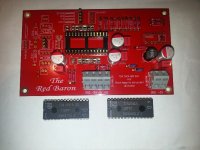
Hey, I picked up a couple of tda1541 chips too.
Which tubes are in your lampizator output stage?
I've got an amanero, and like the waveio I think it might be a bit overkill for the 16 bit tda1541 chip. I'm not sure what I'm going to do with the usb to i2s input yet.
I'm also looking into that fifo buffer for red baron.
Which tubes are in your lampizator output stage?
I've got an amanero, and like the waveio I think it might be a bit overkill for the 16 bit tda1541 chip. I'm not sure what I'm going to do with the usb to i2s input yet.
I'm also looking into that fifo buffer for red baron.
. . . the waveio . . . might be a bit overkill for the 16 bit tda1541 chip.
The WaveIO works superbly with the TDA1541A, esp with a good PSU. Highly recommended.
Which tubes are in your lampizator output stage?
I am using a pair of NOS Tesla E83CC Gold Pin (1:1 to Telefunken ECC803S).
An externally hosted image should be here but it was not working when we last tested it.
- Status
- Not open for further replies.
- Home
- Group Buys
- "Reference" TDA1541A DAC with I2S-BUS architecture