So, like this:
+++
update
uManager Firmware Update, are you sure ?
So... Yes?
and then...
Sören, please be more precise in your instructions.
//
+++
update
uManager Firmware Update, are you sure ?
So... Yes?
and then...
Sören, please be more precise in your instructions.
//
Last edited:
So that would explain why the sound is (always?) shortly interrupted when leaving the uManager i.e. entering command: exit.
//
//
Last edited:
Or do you mean that just entering uManager stops the clock updates?
I.e. after +++ ?
//
Exactly.
Thank you!! 🙂 Now at least there exists a way to resolve our questions and wonderings in this matter.
May the dubbel blind tests begin ;-)
//
May the dubbel blind tests begin ;-)
//
And btw, I2C is a multimaster open drain bus, you can short the lines....
Oups...
 well it has never been my daily job...
The adjustments happens in a interrupt routine, so If you want to test without updates, just enter uManager, updates then stop.... But I doubt that anybody can hear it.
Wow, thanks, but why didn't you say so before?
Just tried it. Accessing the DAM1021 via tera term does not prevent the converter from showing the amplitude drift at 11025 Hz with the triangle wave changing to a "shaved top" triangle. It does however affect the current state of the triangle by setting it to a seemingly arbitrary value in the cycle.
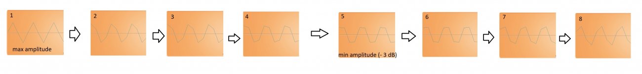
I've attached scope readouts of the characteristic transition. The flatted out saw wave (5), not shot at the perfect position in my image, corresponds to the -3 dB below the initial level (which is given out correctly at the rest of the frequency spectrum).
It does not always cycle through from 1-8 (after which we are back to a clear triangle wave). Instead, it may also "reverse" from the low point (5), cycling through 4-1 backwards again. I've also managed to make it move the other way around altogether by logging into/exiting tera term.
Attachments
Last edited:
Conclusion: Wander/drift does not appear to be the issue here. My guess would be it is a mismatch of the digital audio data readout and the clock.
I managed to record a short snipped at the respective minimum and maximum.
Do you hear I difference? I do.
Dropbox - cycle_minimum(bad).wav - Simplify your life
Dropbox - cycle_maximum(good).wav - Simplify your life
Do you hear I difference? I do.
Dropbox - cycle_minimum(bad).wav - Simplify your life
Dropbox - cycle_maximum(good).wav - Simplify your life
The good file (clean triangle, 11025 hz sine at the same level as rest of frequency range) nulls very well with the source file, the bad file (flatted triangle) does not.
Clock speed does not seem to have any impact on the speed of the cycle. I can adjust the clocking speed of my AD converter (which clocks the entire setup) very precisely.
@ Soeren: What is going on here?
@ Soeren: What is going on here?
Averaged spectrums are almost exactly the same.I managed to record a short snipped at the respective minimum and maximum.
Do you hear I difference? I do.
Attachments
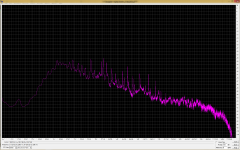
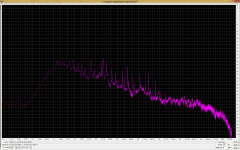
Averaged spectrums are almost exactly the same.
Sure, that would be a much too obvious difference.
I fed both recordings into DeltaWave and compared them to the unconverted original.
After processing with Deltawave the "bad" file nulls a little better than the "good" one. Phase response in the high end was certainly better in the "bad" file. Probably all related to drift rather than the 11025 triangle artifact.
What could be gleaned from the tests and anlysis is that drift is not correlated to the 11025 Hz sinwave issue. These are seperate phenomena.
It might all be a non-issue for purely auditioning purposes after all. Being unable to properly isolate the problems makes it hard to analyse.
And about the scope that you use to check for the converted 11025 Hz wave form - what is that scope sampling rate exactly? Even a toy $15 oscilloscope uses about 1 MHz (1 Msps) sampling rate. A better entry level scope is 1 Gsps. And that is exactly to avoid such artifacts.
It does not always cycle through from 1-8 (after which we are back to a clear triangle wave). Instead, it may also "reverse" from the low point (5), cycling through 4-1 backwards again. I've also managed to make it move the other way around altogether by logging into/exiting tera term.
Would you be able to superimpose the 8 graphs, and check if the zero crossings are aligned?
If the zero crossings are aligned, then it may not be the PLL driven clock shift, possibly something else contributing to the non-triangular shape.
My certain observation so far is that both my singel 1021 and double 1121 (bal stereo) runs fine in xxx-mode without any glitches, pops or ticks. For hours on. I waited 15 mins before moving them to xxx-mode. Its the "R-rated" mode ;-)
//
//
And about the scope that you use to check for the converted 11025 Hz wave form - what is that scope sampling rate exactly? Even a toy $15 oscilloscope uses about 1 MHz (1 Msps) sampling rate. A better entry level scope is 1 Gsps. And that is exactly to avoid such artifacts.
This was a scope plugin analyzing the recording from the AD converter. So the sampling rate is 44,1 khz.
I've got an analog as well as a digital scope, but this artifact shouldn't happen in a DAAD chain.
This is the normal behavior of an ad converter. At 11025 Hz there are only 4 sample points and if dac and adc are not operated with the same master clock, there is drift. And by the way, the 11025 Hz triangle signal has a much higher frequency spectrum than can be reproduced with 44.1 kHz.This was a scope plugin analyzing the recording from the AD converter. So the sampling rate is 44,1 khz.
I've got an analog as well as a digital scope, but this artifact shouldn't happen in a DAAD chain.
- Home
- Vendor's Bazaar
- Reference DAC Module - Discrete R-2R Sign Magnitude 24 bit 384 KHz