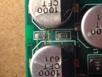
The other positive power supplies are ok, but if had a short on PWR+ the series resistor between two electrolytic capacitors could blow.... It's the 12R 0805 closest to the PCB edge, let me know if you have trouble locating it.
Yep, it looks a little stressed...what are my options? The inner resistor also looks...distressed...🙂
BTW, if you're in Europe you're a real night owl!
Attachments
Yep, it looks a little stressed...what are my options? The inner resistor also looks...distressed...🙂
BTW, if you're in Europe you're a real night owl!
Yes, I'm in Denmark, but also kinda working on US time....
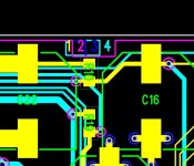
That resistors seems to have exploded, haven't seen that before, but the inner resistors is probably fine.... Even the PCB trace seems to have vaporized so the easiest is probably just to replace it with a 12 ohm leaded (or 10 ohm, not really that critical) part, just connect one to the plus poles of the two capacitors it sit between, closest to the PCB edge, see picture.
Attachments
Okay, many thanks for the quick response. I'll do that tomorrow and let you know the outcome.
Time for bed here....more so in Denmark!
Time for bed here....more so in Denmark!
Those coax spdif signals are sensitive, you need to ensure you got good grounding everywhere, good power and good decoupling. You might want to take a picture and post....
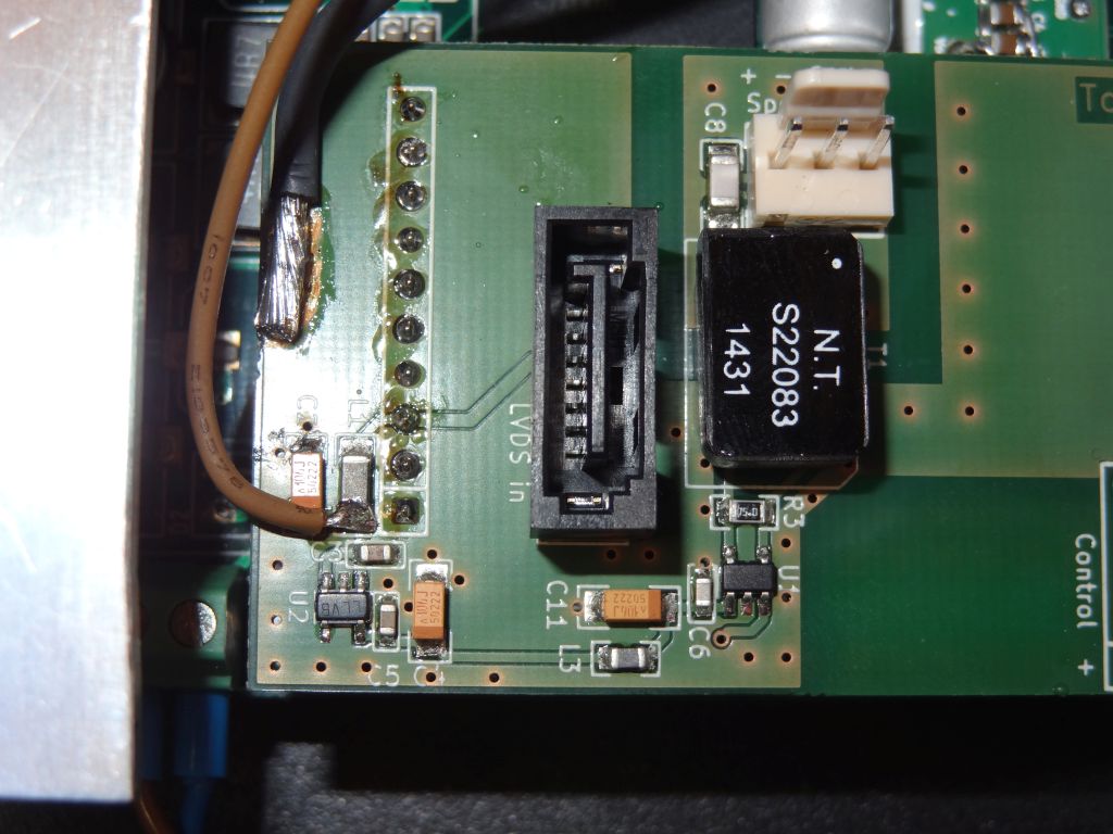
Here is my Input Board. I am feeding the Dac with 5,5V linear reg (the analog part have extra powersupply).
On the left there is a LP5907 for the MAX3280, decoupling is 100nF X7R and 10uF Tantal.
The connector to the DAC board is a smd type on the bottom side. Bottom side has also a GND plane and all GND pins are connected.
Last edited:
Okay, many thanks for the quick response. I'll do that tomorrow and let you know the outcome.
Time for bed here....more so in Denmark!
10R installed. No more offset on J7. But is this correct?
J2 pins:
2 -10.2
3 6.2
5 -4.9
6 4.7
8 3.3
9 1.2
Here is my Input Board. I am feeding the Dac with 5,5V linear reg (the analog part have extra powersupply).
On the left there is a LP5907 for the MAX3280, decoupling is 100nF X7R and 10uF Tantal.
The connector to the DAC board is a smd type on the bottom side. Bottom side has also a GND plane and all GND pins are connected.
That PCB looks fine and should work, the question is how you feed the spdif signal, there is just a connector ?
10R installed. No more offset on J7. But is this correct?
J2 pins:
2 -10.2
3 6.2
5 -4.9
6 4.7
8 3.3
9 1.2
The voltage on J2 pins 2 and 3 should be about the same, just with opposite polarities.... You need to double check the resistor you mounted, if that is correct you need to check the voltage before the resistor.
The voltage on J2 pins 2 and 3 should be about the same, just with opposite polarities.... You need to double check the resistor you mounted, if that is correct you need to check the voltage before the resistor.
Resistor looks fine. Voltage on all the positive pins of the four caps along the edge is 6.5VDC.
Rectifier behind the Power In connector has -10VDC on the - output pin and 6.6VDC on + output pin.
Am feeding the Power In connector with 2x 7VAC each with 200ma. Will try +/- 12VDC now....
...Rectifier won't let more than 7.6VDC through with +/- 12VDC supply.
Am feeding the Power In connector with 2x 7VAC each with 200ma. Will try +/- 12VDC now....
...Rectifier won't let more than 7.6VDC through with +/- 12VDC supply.
Last edited:
Rectifier behind the Power In connector has -10VDC on the - output pin and 6.6VDC on + output pin.
Am feeding the Power In connector with 2x 7VAC each with 200ma. Will try +/- 12VDC now....
2x 7VAC/0.2A is probably not enough....
Think I found the culprit. Connected the +/-12VDC and after a while something began to smell hot. Powered down and the 3.3VDC regulator, U4, was very hot. Left it a while and powered back up - getting even voltage on the A- and A+ but no 3.3V anymore so I guess that must have been damaged in whatever the original incident was and finally expired - there's 11.64VDC in on U4 but no output anymore.
... I have a few of those 1117-3.3's around so will try changing it.
... I have a few of those 1117-3.3's around so will try changing it.
Last edited:
Will soon sync the different board firmware and post them. For now it's just the runtime invert and more robust runtime volume setting....
No plans to add more functionality as I don't really know what to add ?
Please add the possibility to read out current "volume" setting.
And maybe a settable offset between channels so that balance could be implemented.
//
Last edited:
Traffo should be specified at least 2x dc current needed.. so in this case one of the lines 0.35A. I usually go for 2.5 or more when i buy transformers.
Connecting via BNC socket and RG179.That PCB looks fine and should work, the question is how you feed the spdif signal, there is just a connector ?
Source was a Linn Akurate DS and Lumin U1.
With an La Rosita Omega its getting worse, clicks every few seconds...
Have you tried the MAX3280 with the DAM1021?
Please add the possibility to read out current "volume" setting.
+1. Also the ability to configure a max volume limit (I.e. deliberately set an artificial ceiling). I remember several others asking for this not too far back in this thread.
Think I found the culprit. Connected the +/-12VDC and after a while something began to smell hot. Powered down and the 3.3VDC regulator, U4, was very hot. Left it a while and powered back up - getting even voltage on the A- and A+ but no 3.3V anymore so I guess that must have been damaged in whatever the original incident was and finally expired - there's 11.64VDC in on U4 but no output anymore.
... I have a few of those 1117-3.3's around so will try changing it.
The only thing is - that reg supplies the clock. I cannot imagine how that failing would result in voltage offset.
I tend to think you may have failure with the negative 5 volts regulator before the negative polarity Vrefs.
Make sure you are getting he correct voltages from those 5 volts regs before the Vrefs.
+1. Also the ability to configure a max volume limit (I.e. deliberately set an artificial ceiling). I remember several others asking for this not too far back in this thread.
+1 😉
//
Think I found the culprit. Connected the +/-12VDC and after a while something began to smell hot. Powered down and the 3.3VDC regulator, U4, was very hot. Left it a while and powered back up - getting even voltage on the A- and A+ but no 3.3V anymore so I guess that must have been damaged in whatever the original incident was and finally expired - there's 11.64VDC in on U4 but no output anymore.
... I have a few of those 1117-3.3's around so will try changing it.
dont like the sound of that
the regs are usually pretty tough
so id consider that its just overloaded
maybe check for a short/continuity between 3.3 and gnd
if shorted remove the ldo and check again
id worry about the microcontroller and fpga as they will be far less robust than the ldo reg and much harder to replace
Haven't had a chance to go back at it but I'm beginning to think like you here- short between 3V3 and ground. Will remove the ldo tonight and check.
Haven't had a chance to go back at it but I'm beginning to think like you here- short between 3V3 and ground. Will remove the ldo tonight and check.
Are you sure you haven't applied too high voltage at some point ? That's kinda the only thing that could cause both damages, as the 3.3V reg get its power before that broken resistor....
But those 1117's are tough parts, might just be shorted, check your 3.3V wiring.
Last edited:
- Home
- Vendor's Bazaar
- Reference DAC Module - Discrete R-2R Sign Magnitude 24 bit 384 KHz