Just to confirm: the isolated serial interface in J3 is at 3.3V, and the non-isolated serial interface in J10 is 5V, correct?
No correct, the isolated serial interface on J3 is 3.3V CMOS levels, the non-isolated serial interface on J10 is true RS-232 level, just like an old PC serial port.
Assuming that is correct, are there any scenarios where the serial interface could be ruined? As of two nights ago, I was able to bring up uManager via doing "+++" over the serial interface. Last night, I could not bring up the uManager, nor get any output from the serial interface. I'm pretty sure nothing changed. My dam1021 board is not modified (other than soldering on standard pin headers).
I have tried the J3/isolated serial connectors via Raspberry Pi connected with Normundss switch board. Also tried J10/non-isolated to my PC using a cheap FTDI FT232RL serial to USB converter (like like one).
Not sure if I have inadvertently harmed my dam1021 board, or if it's just a matter of operator error. But if the latter, I can't figure out what I'm doing wrong, as it definitely was working. In general I'm pretty comfortable working with serial interfaces.
Statistically, it's an operator error 🙂 But anything can break, although I haven't seen a dead serial port yet.
Side question: where are all the serial commands (and their expected responses) documented? uManager is mentioned in the manual, but none of the "real time" commands are documented. I humbly request that these be added to any future manual revision.
I know they're missing in the dam1021 manual, will add them at some point. In the meantime you can use the dam1121 manual, except for the "P" set phase runtime command, they're the same.
matt_garman,
Is your umanager still inaccessible?
I have experienced periods, especially after updating, where I cannot access umanager.
I panic and turn everything on and off a few times to no avail.
Every time a day or so later as mysteriously as access disappeared it returns.
I bet the same will happen for you.
Hi Rick. I haven't had a chance to test again since my post. Your experience is both comforting and disturbing at the same time.

I guess I'll just keep trying. Non-deterministic bugs are the worst.
Rev3 board, what's the polarity on additional bypass caps? Positive towards the power input right?
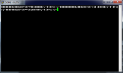
See attached for what I'm getting on the serial port when the board is powered on. Basically a bunch of garbage, but it appears to be consistent garbage. The image represents three or four power cycles of the dam1021 board with serial console attached. Most of the garbage prints when the board is powered on. Looks like this is the string that prints when the board turns on:
So while I'm getting garbage to print at power up/power down, I can't get anything to print after power-on. So in this state I hit "+++" and wait, nothing. Or if I try "I0" (runtime command), nothing.
Thoughts?
Code:
y▒▒▒g▒6Vo▒+Vo▒}▒▒▒▒▒ey=▒j▒Vo[fy=So while I'm getting garbage to print at power up/power down, I can't get anything to print after power-on. So in this state I hit "+++" and wait, nothing. Or if I try "I0" (runtime command), nothing.
Thoughts?
Attachments
Update (just missed the 30 minute edit window): Looks like this cheap FTD1232 doesn't work on the 5V/J10/non-isolated serial port. But it does work on J3/3.3V/isolated serial port. (There is a jumper on this thing to switch between 5V and 3.3V, and I triple-checked that the jumper was set correctly depending on which dam1021 input I was using.)
But I have yet another USB to serial cable, and I got this one working on J10/non-isolated! But I still can't get my Normunds board + Rpi to communicate with the dam1021 via serial.
But I have yet another USB to serial cable, and I got this one working on J10/non-isolated! But I still can't get my Normunds board + Rpi to communicate with the dam1021 via serial.
Update (just missed the 30 minute edit window): Looks like this cheap FTD1232 doesn't work on the 5V/J10/non-isolated serial port. But it does work on J3/3.3V/isolated serial port. (There is a jumper on this thing to switch between 5V and 3.3V, and I triple-checked that the jumper was set correctly depending on which dam1021 input I was using.)
But I have yet another USB to serial cable, and I got this one working on J10/non-isolated! But I still can't get my Normunds board + Rpi to communicate with the dam1021 via serial.
Eeeh, the isolated digital 3.3V serial port and the real RS-232 port have different polarity, all RS-232 buffers are inverting.... So check your USB to serial cable for what kind they are....
The 5V mode of the FTDI is still TTL signalling with no inverted signal, its either high or low and you need to use the 3.3V mode on the isolated port. Remember that true RS232 serial can swing anywhere between +/- 12V which is entirely different altogether than the simple TTL converter.
I do not think that Hifiberry digi+ PRO reclocks anything. It just adds MLCK singal to make it work with dacs that require this. For Soekris is useless.
Actually I believe the HiFiBerry Digi+ Pro uses the clocks to run in Master mode where the bitclock is sent to Pi and used by their driver as the master to produce a better-clocked I2S signal than the Pi can itself. It is not a re-clocker, but a bitclock-based synchronous clocker. A good reclocker should be better, as it can run in a less electrically noisy environment.
For you to know, it seems that Ian is actually working on his reclocker to fit as Rpi or Odroid Hat. In such case Rpi or Odroid with specific software could work as Network Audio Media Renderer which for many of us is ultimate digital audio architecture 🙂
Ian's R-Pi/Odroid add-on is an isolator board with an optional plugin DSD Decoder daughter board. It does not do any reclocking. BUT the new Allo.com Kali is an R-Pi Reclocker that does do a good job cleaning up the I2S out of the Pi. Hopefully they will work together... if not Allo is promising their own isolator board in the future.
Greg in Mississippi
Actually I believe the HiFiBerry Digi+ Pro uses the clocks to run in Master mode where the bitclock is sent to Pi and used by their driver as the master to produce a better-clocked I2S signal than the Pi can itself.
Not looking at code right now, but think that applies to Digi+ and Digi+ Pro. They are both CBM (BCLK master) and CFM (LRCK master)... ie. BCLK and LRCLK are inputs to the Pi from the WM8804. DATA is output from Pi to WM8804. Difference is whether using the single 27MHz clock with non-pro, or the higher quality 22/24MHz (Foxcon????) OSC's on the Pro, fed into the WM8804 to generate the other clocks.......
@Soekris, any news on the implementation of the FSEL input pin? Its a shame that this missing functionality requires me to use an extra cape with reclocking to connect my Beaglebone black. If you could spare some time implementing this I would greatly appreciate it.
Thanks
Thanks
@Soekris, any news on the implementation of the FSEL input pin? Its a shame that this missing functionality requires me to use an extra cape with reclocking to connect my Beaglebone black. If you could spare some time implementing this I would greatly appreciate it.
Thanks
Sorry, but not a high priority feature, it would require major modification to current firmware architecture, which also means time consuming testing....
Hi all.
Just wondering:
Could we expect newer iterations of the firmware for the dam1021?
I really dont miss anything but just wondering if there are some plans developing it even further?
Just wondering:
Could we expect newer iterations of the firmware for the dam1021?
I really dont miss anything but just wondering if there are some plans developing it even further?
Lock problem
@ Soekris,
I made a Input board with MAX3280E (like example in DAM1121 manual) for Spdif 2 input.
It works but at 192kHz it does not lock and at lower rates sometimes i get clicks and the Dam locks again.
Using old circuit for Spdif 1 everything works fine.
@ Soekris,
I made a Input board with MAX3280E (like example in DAM1121 manual) for Spdif 2 input.
It works but at 192kHz it does not lock and at lower rates sometimes i get clicks and the Dam locks again.
Using old circuit for Spdif 1 everything works fine.
Søren - help please!
New 1021 Rev4 board in bal-left configuration. On first powering up got turn-on thump through speaker unlike several previous builds which worked flawlessly. Checked J7 and there is 0.6VDC between pin 1 and pin 2; similar 0.6VDC between pin 4 and pin 3. Other 1021, bal-right in the build, is fine; 0V offset.
Took the board out and connected it to two different power supplies (nothing else at all other than power supply connected) and same 0.6VDC on J7.
What should I check?
Søren - help please!
New 1021 Rev4 board in bal-left configuration. On first powering up got turn-on thump through speaker unlike several previous builds which worked flawlessly. Checked J7 and there is 0.6VDC between pin 1 and pin 2; similar 0.6VDC between pin 4 and pin 3. Other 1021, bal-right in the build, is fine; 0V offset.
Took the board out and connected it to two different power supplies (nothing else at all other than power supply connected) and same 0.6VDC on J7.
What should I check?
Nothing have changed.... Lets do a couple of quick checks first:
Check all power on J2 and report, if ok, then check power directly on the shift registers, easiest is probably on one each of the 1206 capacitors, C166, C169, C172, C175.
Can you check if there is any audio out, like maybe a weak or distorted signal ?
If possible, take a picture of the board and it's connections.
@ Soekris,
I made a Input board with MAX3280E (like example in DAM1121 manual) for Spdif 2 input.
It works but at 192kHz it does not lock and at lower rates sometimes i get clicks and the Dam locks again.
Using old circuit for Spdif 1 everything works fine.
Those coax spdif signals are sensitive, you need to ensure you got good grounding everywhere, good power and good decoupling. You might want to take a picture and post....
Hi all.
Just wondering:
Could we expect newer iterations of the firmware for the dam1021?
I really dont miss anything but just wondering if there are some plans developing it even further?
Will soon sync the different board firmware and post them. For now it's just the runtime invert and more robust runtime volume setting....
No plans to add more functionality as I don't really know what to add ?
Nothing have changed.... Lets do a couple of quick checks first:
Check all power on J2 and report, if ok, then check power directly on the shift registers, easiest is probably on one each of the 1206 capacitors, C166, C169, C172, C175.
Can you check if there is any audio out, like maybe a weak or distorted signal ?
If possible, take a picture of the board and it's connections.
Measured with nothing connected but the power supply, 7.8VAC. Looks like the A+ is an issue. J2 pins:
2 -10.3
3 -0.82
5 -4.9
6 4.9
8 3.3
9 1.19
There is weak audio out.
Measured with nothing connected but the power supply, 7.8VAC. Looks like the A+ is an issue. J2 pins:
2 -10.3
3 -0.82
5 -4.9
6 4.9
8 3.3
9 1.19
There is weak audio out.
The other positive power supplies are ok, but if had a short on PWR+ the series resistor between two electrolytic capacitors could blow.... It's the 12R 0805 closest to the PCB edge, let me know if you have trouble locating it.
- Home
- Vendor's Bazaar
- Reference DAC Module - Discrete R-2R Sign Magnitude 24 bit 384 KHz