No problem here, but out of experience it just sounds a lot better. Interesting comparison:
View attachment 536377
There is a reason that so many folks in this forum use those regs. To me it turns a very good device into an outstanding one.
So you're assuming this comparison on a test jig translates directly to this specific application? I.e. you're taking the chance of buying a set of new, and more expensive, tires for your car, having no idea what size they actually are, and assume they'll just be a perfect fit and will improve your ride?
Are you familiar with the terms trace and cable inductance and capacitance? And ever wondered why local regulation is far superior to having an outboard regulator that's wired in with flying leads?
Yep, thanks again for your support gentlemen, I would not have been able to find the soloution on my own. And big hug to TNT's mom😉
Good to see that you got it to work. 🙂
Perhaps I should have used more clear wording in my reply (see last sentence): http://www.diyaudio.com/forums/vend...magnitude-24-bit-384-khz-488.html#post4642041
Hi Søren,
I have some questions:
1. About the latest firmware (1.05+1.06u), the L000 seems disappeared. Will you add it back? Or it just not practical to know when the signal really lost?
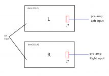
2. About balance (dual dam), if I want to connect to RCA output, should I just connect the first pin (as +ve) and forth pin (as GND) rather than the first and second pin?
3. Will you update the manual to include more detail instruction for balance mode connection in the I2S, SPDIF and the analog outputs (raw J7). In addition, as someone mentioned in 2 pages behind, the instruction for the two RS232 connections should better be described briefly.
Thanks a lot, great work.
I have some questions:
1. About the latest firmware (1.05+1.06u), the L000 seems disappeared. Will you add it back? Or it just not practical to know when the signal really lost?
2. About balance (dual dam), if I want to connect to RCA output, should I just connect the first pin (as +ve) and forth pin (as GND) rather than the first and second pin?
3. Will you update the manual to include more detail instruction for balance mode connection in the I2S, SPDIF and the analog outputs (raw J7). In addition, as someone mentioned in 2 pages behind, the instruction for the two RS232 connections should better be described briefly.
Thanks a lot, great work.
Hi Søren,
I have some questions:
1. About the latest firmware (1.05+1.06u), the L000 seems disappeared. Will you add it back? Or it just not practical to know when the signal really lost?
2. About balance (dual dam), if I want to connect to RCA output, should I just connect the first pin (as +ve) and forth pin (as GND) rather than the first and second pin?
3. Will you update the manual to include more detail instruction for balance mode connection in the I2S, SPDIF and the analog outputs (raw J7). In addition, as someone mentioned in 2 pages behind, the instruction for the two RS232 connections should better be described briefly.
Thanks a lot, great work.
1) It's there, but will only output when signal is lost. Most USB to I2S adapter keep clocks running even without signal and therefore signal is not being lost....
2) RCA is single ended, should connect to signal + and gnd.
3) Manual will be updated when I get to it....
Søren - back in post #4411 you mentioned an example schematic for a better SPDIF using RS422. Any chance you could post a quick schematic?
Also, any update on the timeline for the Rev.3 boards with the 0.01% resistors?
TIA
Also, any update on the timeline for the Rev.3 boards with the 0.01% resistors?
TIA
Re: random sync loss.
It appears this was indeed the source of the problem. Last night I received a 2x15V R-core transformer. That supplies AC to a DIYINHK LT3042 +/-12V supply, which in turn powers the dam1021. Nothing else changed.
I let this run overnight, with the serial console attached, and didn't see any sync loss.
Also interesting is that Hammond 185E16 transformer used to get warm after powering the dam1021 for a while. Not hot, but noticeably warm, maybe 30C or so. Anyway, this new R-core was still "cold" to the touch after powering the dam1021 all night. I used my IR temperature gun on the DC power supply. The choke coil on the positive rail side was the warmest at just under 40C.
I'm currently using a 2x 8V transformer only for power (Hammond 185E16). Is it possible the transformer and/or AC lines are spraying some EMI that is affecting I2S signal integrity (between Amanero and dam1021)?
It appears this was indeed the source of the problem. Last night I received a 2x15V R-core transformer. That supplies AC to a DIYINHK LT3042 +/-12V supply, which in turn powers the dam1021. Nothing else changed.
I let this run overnight, with the serial console attached, and didn't see any sync loss.
Also interesting is that Hammond 185E16 transformer used to get warm after powering the dam1021 for a while. Not hot, but noticeably warm, maybe 30C or so. Anyway, this new R-core was still "cold" to the touch after powering the dam1021 all night. I used my IR temperature gun on the DC power supply. The choke coil on the positive rail side was the warmest at just under 40C.
1) It's there, but will only output when signal is lost. Most USB to I2S adapter keep clocks running even without signal and therefore signal is not being lost....
2) RCA is single ended, should connect to signal + and gnd.
3) Manual will be updated when I get to it....
My case is like the figure shown. So it must be connected like "B"?
Attachments
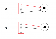
My case is like the figure shown. So it must be connected like "B"?
Yes, like B, + and gnd only.
Two questions:
(1) Is there a header/through hole that is common with the on-board LED? When I put my dam1021 in a case, I'd like to have that status LED visible on the outside.
(2) For adding capacitance to VREF: I have the revision 3 board, which has the convenient through-holes. But I noticed the four rows have only three pair of through-holes each. It looks like everyone with earlier board revisions added 16 (4x4) capacitors to VREF... so does this mod only call for 12 (3x4) caps for revision 3 boards?
Also, does someone have a link to one of the pictures that shows correct polarity for VREF caps? I know it's been posted before, just don't have the link handy...
Thanks!
My case is like the figure shown. So it must be connected like "B"?
soren how to make balanced output for each channel as one board?
Is it there in the new firmware?
Can we have crossover filters: LPF,BPF,HPF with LR4 in the new firmware?
running the dam 1021 at +/-10V. As per the info on the site its mentioned that it can use anywhere between +/-7 to 15V DC but what are the disadvantages of running at 10V will there be any sonic difference?
Don't worry you.Two questions:
(1) Is there a header/through hole that is common with the on-board LED? When I put my dam1021 in a case, I'd like to have that status LED visible on the outside.
(2) For adding capacitance to VREF: I have the revision 3 board, which has the convenient through-holes. But I noticed the four rows have only three pair of through-holes each. It looks like everyone with earlier board revisions added 16 (4x4) capacitors to VREF... so does this mod only call for 12 (3x4) caps for revision 3 boards?
Also, does someone have a link to one of the pictures that shows correct polarity for VREF caps? I know it's been posted before, just don't have the link handy...
3x4 C mod Vref is sufficient. And It will be much more comfortable to make it than v1 and v2 board version.
C polarity power on the board and measured with a multimeter. O measure continuity to ground with power OFF.
Sound differences can come with 15v disadvantages. Voltage regulators have heat protection and by excessive heat, start acting giving worse features than Datasheet.running the dam 1021 at +/-10V. As per the info on the site its mentioned that it can use anywhere between +/-7 to 15V DC but what are the disadvantages of running at 10V will there be any sonic difference?
Don't worry you.
3x4 C mod Vref is sufficient. And It will be much more comfortable to make it than v1 and v2 board version.
C polarity power on the board and measured with a multimeter. O measure continuity to ground with power OFF.
Is there a guide to add caps on the v2 boards?(pictures?)
Two questions:
(1) Is there a header/through hole that is common with the on-board LED? When I put my dam1021 in a case, I'd like to have that status LED visible on the outside.
Yes, there is. It's the PWRLED pin on J3.
Wasn't the Vref mod incorporated is the V3 board?
glt's blog has a nice write-up of the VREF mod. If you scroll down to the near-bottom, there is this comment from Paul (timestamp July 25, 2015 at 04:31):
...
From simulations I’ve done, the stock [revision 1] vref has about 5.8mV ripple under load. Adding 470uF polymer across the output cap of the buffer reduces this to 0.4mV. Søren’s “factory” mod reduces ripple to 1.2mV which brings a major improvement over standard, but is not 100%. Adding a further 470uF across the stacked 22uF/47uF caps or Søren’s mod should lower the ripple to 0.27mV.
The differing levels of ripple result in clear, measurable differences in jitter and spurious tones in the output of the DAM. Søren’s mod plus additional capacitance is possibly the best of the straight forward mods.
Based on the timestamp, I'm pretty sure that the factory mod he's referring to is revision 2 (since revision 3 was end of 2015/early 2016).
But then Søren said this in post #4291 (emphasis added):
I now use a custom resistor value on all new boards, so all the 3M01 "fine adjust" resistors will be removed. That leaves space for an additional 300 uF ceramics on each vref.
...
So, if I'm piecing this info together correctly, VREF capacitor values are:
Revision 1: X uF
Revision 2: X + Y uF
Revision 3: X + Y + 300 uF
Not sure what X and Y are. Also not sure if X+Y+300 is "enough". But, with those revision 3 through-holes, it looks to be a trivial mod, and presumably it can't hurt (right?).
matt: Soekris have posted all info regarding vref differences here:
For people who want to use two boards from different production lots in balanced mode here is how each of the four vref buffers look like from the factory:
Original rev1: 10R series resistors, 22 uF output capacitor, 330 pF feedback capacitor and 499R feedback resistor
Factory upd rev1 and prod rev2: 0.1R series resistor, 47 uF output capacitor, 499R resistors mounted in both capacitor and feedback resistor position, creating an effective 0.050R vref buffer output impedance.
Prod rev3: 0.1R series resistor, 47 uF + 3x 100 uF output capacitors, 1K00 resistor mounted in feedback capacitor position (orange), 301R resistor mounted in feedback resistor position (yellow), creating an effective 0.025R vref buffer output impedance.
Will that make any difference?You can also get 47uF X5R 6V3 ceramics in 0805 size, easy to stack on top of existing capacitors….
- Home
- Vendor's Bazaar
- Reference DAC Module - Discrete R-2R Sign Magnitude 24 bit 384 KHz