I am planning to do all DSP/crossovers computer side, mapping each speaker channel to an individual digital output on a multi digital output pro sound card. Then probably multiple DIY DACs per channel.
Me too, but I will use an exa21 to convert usb to 8 channels of i2s to 4 soekris dacs.
Yes you are right. Thanks.
One of the metal ends of the resistor is loose and I had to push one dmm tip right into the side of it to get a reading. 6k04r it is.
Could this be my problem? The resistor connect 2 isolated parts of the board it seems.
I dont know.
That resistor is connected between the MCU and the emitter of a transistor which is the drive circuity for the mute circuit. It mutes the DAM by forcing the TL431 output to 0V,
[/QUOTE
With the crossovers done in the computer, how do you propose assigning the frequency ranges to each speaker?
Do filtering in DAM!
//
Do filtering in DAM!
//
Has anyone achieved that? That was my main reason to be interested in the dac but lost interest as i could not see it happen- please correct me if wrong
Sören claims it should now be possible. Haven't heard any tales of success yet - none failed either.
//
//
An easy application to make filter curves, like with mlni dsp, would be great... Right now filter brewing is a bit hard to understand, for me, at least
Do filtering in DAM!
//
At this point, like the manual, that is just talk.
So much easier to implement, change, and test if done in the computer. I suppose once the final crossovers are decided upon, it MAY be possible to load them into the dam at some point...
Input DC voltage without opamps?
Hello,
What's the optimal input DC voltage for the DAC with the opamps for balanced output removed ?
With the opamps removed there's no need for that higher voltage (11-12vdc), with a lower voltage the regulators can work more relaxed (cooler).
Regards,
Danny
Hello,
What's the optimal input DC voltage for the DAC with the opamps for balanced output removed ?
With the opamps removed there's no need for that higher voltage (11-12vdc), with a lower voltage the regulators can work more relaxed (cooler).
Regards,
Danny
Houston - we got sound. 😀That resistor is connected between the MCU and the emitter of a transistor which is the drive circuity for the mute circuit. It mutes the DAM by forcing the TL431 output to 0V,
This was the problem.
Searched the bin and found a couple of smd resistors parallelling to approx 6.5kohm. (nearest 6040r I could find).
Now it works again.
How important is the value 6040r here? Will order some in a couple of days.
Thanks guys !
Houston - we got sound. 😀
This was the problem.
Searched the bin and found a couple of smd resistors parallelling to approx 6.5kohm. (nearest 6040r I could find).
Now it works again.
How important is the value 6040r here? Will order some in a couple of days.
Thanks guys !
Ah nice one you fixed it. 6040r not that critical. 6,5k will do until you get the correct value.
Houston - we got sound. 😀
This was the problem.
Searched the bin and found a couple of smd resistors parallelling to approx 6.5kohm. (nearest 6040r I could find).
Now it works again.
How important is the value 6040r here? Will order some in a couple of days.
Thanks guys !
Glad that you have sort it out. Me personally I got rid of 27.4k resistor after finding that DAM will mute every time my DEEP-FRIER trigger?!
Lately I got busy in applying this final Vref mod: 16 x opa365:
no big 3300+uF caps (turn DAM1021 into boombox) and no ceramics, only original buffer layout multiplied by 16 (one for each shifter) charing common +- 4v ref.
cheers
Danny
Attachments
Hello,
What's the optimal input DC voltage for the DAC with the opamps for balanced output removed ?
With the opamps removed there's no need for that higher voltage (11-12vdc), with a lower voltage the regulators can work more relaxed (cooler).
Regards,
Danny
I have powered DAM on 2 x 6.3v AC, 9v DC per rail and 3.3v Reg is running cool (12vDC was hot).
Cheers
Danny_C
@Soekris
I want to build an active speaker and installing in each box a board as a crossover, but for that i would have to load different filters for the left and right channel.
Is it possible to implement this in the next Firmware?
I want to build an active speaker and installing in each box a board as a crossover, but for that i would have to load different filters for the left and right channel.
Is it possible to implement this in the next Firmware?
As stated long time ago, the dam1021 resistor network direct out is a voltage source with 625 ohm in series. If you want to lower the output level you simply just shunt the output with a suitable resistor....
Some random thoughts.
On the volume control;
When I connect the DAM directly to the power amp I usually end up with volume settings V-15 to V-20. In view of
the realization of the volume control in the DAC ladder is convenient but a waste of resources. The expensive MSB resistors are never used, and the specs are thus (theoretically) worse than if you attenuate after the ladder (for the volume only, no precision resistors are needed) or lower Vreff.
Perhaps a future revision could realize the coarse part of the volume control outside the ladder.
So I did a little test. First plot is with DAM volume set to -21dB

Second plot DAM volume set to -1dB and a 69 Ohm shunt resistor resulting to the same output level.

As you see THD+N is only half in the later case, however with a very different distribution of the magnitude of the harmonics.
Last edited:
I have powered DAM on 2 x 6.3v AC, 9v DC per rail and 3.3v Reg is running cool (12vDC was hot).
Cheers
Danny_C
I plan on using the opamp outputs for headphones,can I still use 2x9VDC,
Will it be enough?
Glad that you have sort it out. Me personally I got rid of 27.4k resistor after finding that DAM will mute every time my DEEP-FRIER trigger?!
Lately I got busy in applying this final Vref mod: 16 x opa365:

no big 3300+uF caps (turn DAM1021 into boombox) and no ceramics, only original buffer layout multiplied by 16 (one for each shifter) charing common +- 4v ref.
cheers
Danny
So you change the OP amps for a better one?
//
So I did a little test. First plot is with DAM volume set to -21dB
Second plot DAM volume set to -1dB and a 69 Ohm shunt resistor resulting to the same output level.
As you see THD+N is only half in the later case, however with a very different distribution of the magnitude of the harmonics.
Nice test.
I definitely prefer the second, looks more like a nice declining FFT of a triode
Time to finish my autoformer and do the volume controml with that. 🙂
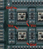
Perhaps helpful also for others until we (hopefully) get the schematics:
I photoshoped the traces and vias that are on the backside of the DAM (rev1) as transparent red on the front side. What is missing are the traces on the front beneath the components or covered by the white paint and on the back the ones that are under the sticker.
I photoshoped the traces and vias that are on the backside of the DAM (rev1) as transparent red on the front side. What is missing are the traces on the front beneath the components or covered by the white paint and on the back the ones that are under the sticker.
Attachments

- Home
- Vendor's Bazaar
- Reference DAC Module - Discrete R-2R Sign Magnitude 24 bit 384 KHz