Blown OPA365 (OAVQ)
Hi bambadoo, it's look like you have blown one of the buffer IC (next to U33 mark). Have you checked polarity of (to late now)big caps before powered?
If you are lucky you will have to replace only one buffer IC and/or -5v reg.
btw If any of you guys are thinking that all this mods are to much for you and thinking to buy a new ver2 board (Vref mod done out of the box) and willing to sale your ver1 unmodified board please PM me (only 0.01%)
thank's
Danny
Took the plunge. Did the vref mod. First 16x caps mod from hifiduino.
Tested the dam. Works ok.
Then the other 0r, 0.1r mod.
And also the 27k4r poweron/poweroff mod.
Measured resitance after with a dmm. Seems ok.
Power on and no sound. Can connect to umanager with no problems. The dam got signal and lock but unfortunately no sound.
Late here now. Will do some more testing in a day or two..
Hi bambadoo, it's look like you have blown one of the buffer IC (next to U33 mark). Have you checked polarity of (to late now)big caps before powered?
If you are lucky you will have to replace only one buffer IC and/or -5v reg.
btw If any of you guys are thinking that all this mods are to much for you and thinking to buy a new ver2 board (Vref mod done out of the box) and willing to sale your ver1 unmodified board please PM me (only 0.01%)
thank's
Danny
Attachments
Every "voltage" at J2 is ok.Check the vref voltages for starters, its the first thing I did upon poweron after performing my 16 cap mod.
However I got about 3-4mv in the vref 😡 What could be wrong? Desoldered the vref mod for one channel also. No change.
The polarity for the 16caps are ok and just as described from hifiduino site.
One good thing. The poweron/off issue is gone... Absolutely silence since nothing arrive at the output..
Last edited:
bambadoo, for each OPA365, check that it is receiving power and that it has either +4V or -4V on its '+' input, which will indicate that the reference voltage is present.
Then it isn't superior in my application...
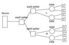
Your application can't be solved with one DAM either. If you don't use 4 boards. And you could use 3 toslink splitters to create 4 Toslink lines form one source... so.. maybe.
//
No way to get 8 channels of toslink out of my computer. My exa21 will, however, take the usb out and split it into 8 i2s channels.....
Get 3. But the first might need to be active.
Digital Toslink Optical Fiber Audio Y Splitter 1 to 2 Cable Adapter s PDIF HDTV | eBay
//
Digital Toslink Optical Fiber Audio Y Splitter 1 to 2 Cable Adapter s PDIF HDTV | eBay
//
bambadoo, for each OPA365, check that it is receiving power and that it has either +4V or -4V on its '+' input, which will indicate that the reference voltage is present.
Hi, will check later today but I suspect that the reference voltage is not present.
But I have some additional information.
When I did the mods (between the 16 cap mod which worked and the rest of the vref mod including the poweron/off 27k4r resistor mod) I also thought of soekris early post regarding the 6 main 820 uf caps.
http://www.diyaudio.com/forums/vend...magnitude-24-bit-384-khz-178.html#post4225082
I have some of them on hand so of course I could make the switch.If you insist to improve the onboard power supply, try replacing the 6 electrolytic capacitors with aluminum polymer types, 1000u 16V exist in same 10mm smd footprint
But I did not manage to remove the original caps. I tried with one. One of the RC filter caps.

Up in the right corner. I started using a heater gun for the purpose and had to give up.
Could this be the fault? Have I toasted the cap (overheat inside) and made sure the vref voltage is not present?
If so - would really change these caps (in good manner) make it work again?
It measures approv 10.5Vdc across its terminals.
bambadoo, the RC caps supply the output opamps, so if you are using the raw output they shouldn't matter - that is unless they are pulling the supply down. As you are measuring 10.5Vdc, I would expect this not to be the cause of your problem.
You need to measure that you have got +/5V for the opamps, and +/-4V for the references. This will give an indication of where the problem is.
You need to measure that you have got +/5V for the opamps, and +/-4V for the references. This will give an indication of where the problem is.
bambadoo,
I found one can just PULL those electrolytics off of the board. The big ones after the rectifier were especially easy.
My intention was to destroy them by pulling off the aluminum jacket and then having better access to the solder points but as I did this I found they simply came off with firm even pressure. No yanking! Pull them off in the direction of the pads so you pull against one tab at a time. Look at a spec sheet for where the solder points are, I worry an explanation within this post will not be accurate enough.
I did pull up a solder pad on the caps after the 5 volts reg but luckily it was a ground pad and is easy enough to work around.
If you do not use the balanced buffer output then you can experiment with the two furthest from the end which only affect those op-amps. If you cannot get those to come off with my "method" your board may not be as compliant as mine was.
I attempted to use a soldering iron but the pads are very difficult to touch and I worried I could do more damage to other components with the heat.
I removed all of the electrolytic caps, this way, on my board.
Worth a try?
Last edited:
bambadoo, the RC caps supply the output opamps, so if you are using the raw output they shouldn't matter - that is unless they are pulling the supply down. As you are measuring 10.5Vdc, I would expect this not to be the cause of your problem.
You need to measure that you have got +/5V for the opamps, and +/-4V for the references. This will give an indication of where the problem is.
I can find +-/5V for the opamps. However nothing for the references. Well approx 1.5mv
Or maybe it is the 27k4 mod itself?
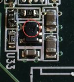
This little bastard here. (With a red ring) Can this be fried? I desoldered and try to "Ohm" it. Infinite. Is it a resistor or something else? It is too small for me to tell.
Attachments

Last edited:
I'm afraid I can't tell what it is, though it does look like a resistor, or maybe a bead. Soren will know.
You measured +/-5V .... was that at the outputs of the regulators, or the inputs to the opamps AND references? The references are TL431s if I remember correctly.
You measured +/-5V .... was that at the outputs of the regulators, or the inputs to the opamps AND references? The references are TL431s if I remember correctly.
Speaker.
If your filters will be implemented in DAM, you can simply connect the data line from TOSLINK receiver into all dacs in parallel. No need for optical splitters, although it implies all DAM boards need to be located close to each other.
If you want to do filtering in computer, then of course you will need separate channels to the DACs.
That should be a 6k04 resistor. EIA-96 code 76B = 6k04This little bastard here. (With a red ring) Can this be fried? I desoldered and try to "Ohm" it. Infinite. Is it a resistor or something else? It is too small for me to tell.
Yes you are right. Thanks.
One of the metal ends of the resistor is loose and I had to push one dmm tip right into the side of it to get a reading. 6k04r it is.
Could this be my problem? The resistor connect 2 isolated parts of the board it seems.
I dont know.
One of the metal ends of the resistor is loose and I had to push one dmm tip right into the side of it to get a reading. 6k04r it is.
Could this be my problem? The resistor connect 2 isolated parts of the board it seems.
I dont know.
Last edited:
Speaker.
I am planning to do all DSP/crossovers computer side, mapping each speaker channel to an individual digital output on a multi digital output pro sound card. Then probably multiple DIY DACs per channel.
- Home
- Vendor's Bazaar
- Reference DAC Module - Discrete R-2R Sign Magnitude 24 bit 384 KHz