Because, you usually dont unplug/replug that much, and when you do, then you use the tool (which i already own). Also, there are third party u.fl-cables/connectors which is much cheaper than the japanese originals.
As said, it looks better, feels better, and are just simple to work with. Plus its not that they are expensive when you look at the whole project.
Also, i have never broken a u.fl connector - probably because i always use the tool.
Boutique hifi 🙂
//
Hi!
What's up with the official users manual?
Greets:
Tyimo
I think many of us are wondering as we try to wait patiently.....
Attached is a quick dam1021 R-2R DAC drawing with connector pinouts. The more experienced DIY'er can get started with that, but I will also be doing a better and more detailed manual over the weekend.
Not wanting to appear impatient but the above was posted two weekends ago and we are rapidly approaching a third weekend.
It would be nice to see some documentation of the board beyond what is scattered across this thread. Headers for indicator LED's have been mentioned but no details as yet, for example.
Even a draft copy would be better than nothing...
Back with my WaveIO.
Also with the WaveIO ther a clicks, not as loud as reported from others, but still very audible. Also are sometimes a few seconds at the beginning of a song missing. Can't say much more to the sound as it looks like the dac only synchronizes to the WaveIO when connect in the right direction to the multiple outlet socket. That may be related to the filters used.
Today I spent the evening trying to connect the dac with an USB to serial adapter. It says it has 5V TTL level, but did not work anyway. I will not do much listening before these issues are solved.
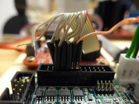
Attached is another picture of the connections from the WaveIO. It does not use the same pinout as dam1021. But I still would like to get one isolator out of the way. I have seen u-fl adapter boards in other projects (acko, ian ?), may be one of them can be used here as well or any of the usual suspects is willing to help out😉
Well time to have some sleep...
Torsten
Also with the WaveIO ther a clicks, not as loud as reported from others, but still very audible. Also are sometimes a few seconds at the beginning of a song missing. Can't say much more to the sound as it looks like the dac only synchronizes to the WaveIO when connect in the right direction to the multiple outlet socket. That may be related to the filters used.
Today I spent the evening trying to connect the dac with an USB to serial adapter. It says it has 5V TTL level, but did not work anyway. I will not do much listening before these issues are solved.
Attached is another picture of the connections from the WaveIO. It does not use the same pinout as dam1021. But I still would like to get one isolator out of the way. I have seen u-fl adapter boards in other projects (acko, ian ?), may be one of them can be used here as well or any of the usual suspects is willing to help out😉
Well time to have some sleep...
Torsten
Attachments
Today I spent the evening trying to connect the dac with an USB to serial adapter. It says it has 5V TTL level, but did not work anyway. I will not do much listening before these issues are solved.
This DAC can only talk to a "real" RS-232 serial port, not one that runs on TTL levels. You need a proper USB to Serial adapter (one that has a DB9 connector) and a proper cable.
But I still would like to get one isolator out of the way. I have seen u-fl adapter boards in other projects (acko, ian ?), may be one of them can be used here as well or any of the usual suspects is willing to help out😉
Will not be difficult to design a small interface PCB having the correct pin out.
Regards,
Enrico
Short somewhere ? What is connected ?

Min connected, rs232, toslink and rca out.
Thing is I started out with the power led and input power, and it already doing the blink once.
Just doubled check and nothing short any where.
Appreciate your kind advise
Only rs232, toslink input and rca out.Short somewhere ? What is connected ?
Thing is I started with power input and led first and it was already blinking once before I connected anything else.
Any chance the board could be faulty?
Only rs232, toslink input and rca out.
Thing is I started with power input and led first and it was already blinking once before I connected anything else.
Any chance the board could be faulty?
It might help if you connect a GND at the power connector.
ADD:
It looks like you have not read the power supply requirements and have hooked up a +10VDC to one side and GND to the other.
You must have + and - DC supply and GND connected to middle pins of the power connector for the board to work.
My fault diagnosis : User Error.
Last edited:
+ and - DC are connected but not ground. Will give it a try. Thx!It might help if you connect a GND at the power connector.
ADD:
It looks like you have not read the power supply requirements and have hooked up a +10VDC to one side and GND to the other.
You must have + and - DC supply and GND connected to middle pins of the power connector for the board to work.
My fault diagnosis : User Error.
Added the ground lines and I hv blinking lights now. Now to get a lock on the toslink input+ and - DC are connected but not ground. Will give it a try. Thx!
Min connected, rs232, toslink and rca out.
Thing is I started out with the power led and input power, and it already doing the blink once.
Just doubled check and nothing short any where.
Appreciate your kind advise
1) As already said, power is incorrect connected and it can't work without correct power, both + and - referred to GND.
2) You can't connect a LED directly, you need a current limiting resistor in series.
3) And you can't connect the RCA plugs like that, you have to connect them between OUT+ and GND.
Excuse the fact that this is not a solely SOEKRIS question - but back to uFL connectors - having never used these I was taken by surprise when it was mentioned one needed a tool to separate them. So I looked into getting the tool and then I see a tool for inserting the connector!
From someone familiar with these please let me know if there is a special technique to getting them connected. Does one need a tool?
I will be greatly appreciative!
From someone familiar with these please let me know if there is a special technique to getting them connected. Does one need a tool?
I will be greatly appreciative!
I say, you only need one to remove them, not to connect them.
You can even remove the connectors without the tool - but there is bigger risk to damage the connectors.
You can even remove the connectors without the tool - but there is bigger risk to damage the connectors.
Excuse the fact that this is not a solely SOEKRIS question - but back to uFL connectors - having never used these I was taken by surprise when it was mentioned one needed a tool to separate them. So I looked into getting the tool and then I see a tool for inserting the connector!
From someone familiar with these please let me know if there is a special technique to getting them connected. Does one need a tool?
I will be greatly appreciative!
For insertion, you just need to make sure it is PERFECTLY flat, and square to the mating connector. If it's a off, it will still mate, but you can damage the connector that way.
There is an error either in the above table or in the dam1021_mech_con.pdf. The roles of INP SLCT0 and NP SLCT1 are swaped....
Input Select is:__INP SLCT0___INP SLCT1
Auto_____________N-C_______N-C
I2S______________GND______GND
SPDIF1 (Coax)_____N-C_______GND_____(Sensitive LVDS receiver)
SPDIF2 (Toslink)___GND_______N-C______(Standard 3.3V digital level)
Chrisnew : the output for the RCAs is the 4 vias in the middle between the balanced output ! You connected the Single Ended on the Balanced output ! Look at the shematic : link in first page of this thread !
Can you photograph the Powersupply please ? And give the unloaded voltage at the output of your PS ?
Can you photograph the Powersupply please ? And give the unloaded voltage at the output of your PS ?
- Home
- Vendor's Bazaar
- Reference DAC Module - Discrete R-2R Sign Magnitude 24 bit 384 KHz