I do not remember the source but I have these graphs that compare BUT and LR filters. Maybe someone here could 'decode' what they're supposed to mean (good / better / best etc.).. in theory MTM LR will have no benefit with regards to crossover lobing....
Attachments
Last edited:

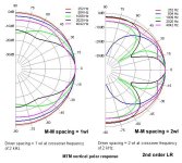
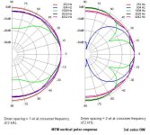
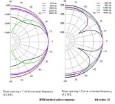
Ok. Take a look at the crossover, so just look at the black traces since they are for 2kHz. All the Butterworths have fairly even vertical response and all the LR have nulls above and below.
The nulls are what normal lobing looks like in any case. Since the Butterworths are not symmetrical, flipping the lobing pattern tends to fill in the gaps. LR is symmetrical to start with, so flipping them makes no difference.
(I should clarify that when I said LR MTM had no benefit, I was only saying that it had the same pattern as TM, FWIW)
Last edited:
The slopes are symmetrical around the crossover frequency, but the lobes aren't symmetrical around the 0 degree axis. The reason is phase, which is symmetrical and it tracks, but with a fixed 90 degree offset.
looking at the picture of the BUT18 at 2k crossover, one WL CtC spacing : the lobbing seems symetrical on a large frequency flat magnitude (spl) in the vertical 15° around the axis point. Looks good to me. What do you think ?
@newvirus2008 , What are the dotted line, please ? -3 dB i.e. beginning of the non flat magnitude below that dotted line
@AllenB , is there a difference with these different filter slopes on the horizontal off axis with MTM over MT, please ? Or is the same cause the drivers are vertically alligned ? I mean that when seated, thee horizontal sweet spot width is what most want to be the largest as possible. So I wonder if a slope is better than another for that or if it is just a layout baffle and listening distance question ?
It is similar at different horizontal axes, the lobing still happens top to bottom like a three dimensional shape. There will be some smaller variations, this is because the distances between them change a little off horizontal axis, and the levels between them change a little off horizontal axis.
I think that's the -3dB reference, as you've already guessed.What are the dotted line, please ? -3 dB i.e. beginning of the non flat magnitude below that dotted line...
@diyiggy,
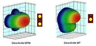
This 3d graph should help clarify things about directivity behaviour.
If you look at the vertical polar Newvirus linked you will quickly identify what they mean once in 3D.
As was already stated the horizontal behaviour is the same as for a single driver ( high end will depend of the tweete/horn own behaviour though).
Attachments
Last edited:
I think that's the -3dB reference, as you've already guessed.
For 12db/octave fiters yes, for 24db/octave it is -6db.
If someone want to investigate a bit further about the effect of CTC spacing, 'Horbach-Keele' second white paper give nice explanation on vertical directivity 'shaping' by playing with this parameter.
The fig 3 explain what to expect and the serie of graph given show the overall vertical pattern to be expected in relation to ctc spacing. With the 3D 'balloon' rendering given in post #49 you can estimate the rendering ( eg: the overall shape of the 3D rendering of post #49 is close to the e) or d) in fig2 of the paper).
https://www.xlrtechs.com/dbkeele.co...ear Phase Digital Crossover Flters Part 2.pdf
krivium, thanks for the plots. They show the 3d nature of it.
However I'm concerned they could be misleading in answer to diyiggy's question and would like to ask for clarification. I'd expect the polars to be the same for MT and MTM for a symmetrical crossover, exactly at the crossover frequency, when the drivers are at a directivity match... What you've shown looks like it has other factors going on.
However I'm concerned they could be misleading in answer to diyiggy's question and would like to ask for clarification. I'd expect the polars to be the same for MT and MTM for a symmetrical crossover, exactly at the crossover frequency, when the drivers are at a directivity match... What you've shown looks like it has other factors going on.
Yes this pattern are not focused on any frequency, they represent the overall directivity shape in 3D and the colours used the relative SPL.
I don't know what kind of filters were used either for MTM or TM, that said as i played extensively with simulation of MTM in the past i'm pretty sure the filter used here is 18db/ octave for MTM.
As well it should be noted the colour pattern is equal to intensity ( spl) and gives an idea of the recommended listening axis but doesn't take into account the directivity behaviour of the tweeter. To say it differently it was simulated with ideal omni driver behaviour. In reality if a waveguide was used the overall shape would track the waveguide own directivity rather than the overall shape presented here.
But with all this limiation in mind i've found it is interesting 3D rendering nevertheless. It made me understand why it is often recommende to listen to TM either on tweeter axis or a litlle below. As well why people insist on the symmetry of vertical behaviour of MTM and why you should listen them with tweeter at ear height ( at least in close proximity).
If your premise is that you can measure an MTM and then flip it upside down and measure again and the results will be different, then I think you better reset your understanding. 🙂It is similar at different horizontal axes, the lobing still happens top to bottom like a three dimensional shape. There will be some smaller variations, this is because the distances between them change a little off horizontal axis, and the levels between them change a little off horizontal axis.
The only (real world) possibility for that to happen would be if one of the MTM "M" drivers was faulty or had a significant difference from the other one.
The symmetrical polar response of an MTM is intuitively obvious from observation. It doesn't need measurements to demonstrate it.
And it matters not what type of crossover is employed, BW, or LR, or whatever.
(Assuming the microphone is centered on the tweeter.....which is obviously the design-axis of an MTM.)
Many MTM designs are configured into a tower system where there is considerably more baffle below than above. That would an exception because the "baffle" itself is not symmetrical.
Dave.
Do you know where I could read details of that decision?
If you are talking about Joe, it is in the history of Speaker Builder. Some subsequent MTM prohjects he id, did not use 3rd order.
In my big MTM i do not have loving, the passive XO is 4th order acoustic, 1st order works fine active.
dave
Last edited:
Kef104/2 Ref.
the MTM's Ms' are not treated symetric about the filter and impedance/magnitude... I assume one is nearer to the the floor and anyway the top midwoofer (cut off around 150 hz to 3 k hz) is centered at ears heigth (so tweeter below, not saying the lower near the floor woofer of Mtm)

the MTM's Ms' are not treated symetric about the filter and impedance/magnitude... I assume one is nearer to the the floor and anyway the top midwoofer (cut off around 150 hz to 3 k hz) is centered at ears heigth (so tweeter below, not saying the lower near the floor woofer of Mtm)
...but I have these graphs that compare BUT and LR filters.
Any chance of curves with even closer spacing. I am interested in ¼ WL spacing.
dave
Dave, yours should be sound fine because of that M-Fr-M, (so very low cut off and drreaming CtC spacing) but most designs are made with higher cut offs, and anyway some sounding fine enough (Kef 104/2 -you dislikes from memory, but I liked a lot- or some several Snell and so on ... all the so on not sounding always fine though ! )
I am confident yours is sounding better than a Living voice MTM, though.
I am confident yours is sounding better than a Living voice MTM, though.
Then it's not an MTM. (Not in the generally understood definition anyway.)Kef104/2 Ref.
the MTM's Ms' are not treated symetric about the filter and impedance/magnitude... m)
Dave.
- Home
- Loudspeakers
- Multi-Way
- realizing a D'appolito crossover with DSP