A'af to quote your email:
Are you saying you never agreed to this?
You don't seem to understand what I have said:
a) We cannot say if your chips are fake or not. Even TI will not guarantee authenticity unless they can show a verifiable flow of product from their factory to customer. You have no way to prove they are genuine. Equally it cannot be proved that they are fake, although production dates suggest that is the case.
b) Whether they are faked or not is really beside the point. The technology seems to allow the chip to replicated from the original wafer, so the fakes should be close to identical to the original, except perhaps for the laser trimming and the determination of grades.
c) You have offered these chips as high performance grade, and charge accordingly. The chips you supply range from substandard to border-line very good on Bernhard's scale.
It's hardly surprising that those who have received the substandard chips feel aggrieved. They are paying top dollar for low performance.
No problems, please send back to me all, and i will give you a full refund
after i accepted your package.
Are you saying you never agreed to this?
You don't seem to understand what I have said:
a) We cannot say if your chips are fake or not. Even TI will not guarantee authenticity unless they can show a verifiable flow of product from their factory to customer. You have no way to prove they are genuine. Equally it cannot be proved that they are fake, although production dates suggest that is the case.
b) Whether they are faked or not is really beside the point. The technology seems to allow the chip to replicated from the original wafer, so the fakes should be close to identical to the original, except perhaps for the laser trimming and the determination of grades.
c) You have offered these chips as high performance grade, and charge accordingly. The chips you supply range from substandard to border-line very good on Bernhard's scale.
It's hardly surprising that those who have received the substandard chips feel aggrieved. They are paying top dollar for low performance.
actual on ebay:
Just found this on ebay;
http://cgi.ebay.de/ws/eBayISAPI.dll?ViewItem&rd=1&item=110247538259&ssPageName=STRK:MEWA:IT&ih=001
In short: DAC IC PCM63P-K (Well Recycled) , Brand: BB, Package: DIP
100% tested before shipping. Gurantee exchange if it is fault.
Company Background: Sisitronic is a Hong Kong based company with China offices in different provinces. We supply a wide range of electronic components, specialized in IC including Audio IC, Power Management IC, Consumer Electronic IC, etc. Our aim is to supply any parts which are difficult to be sourced in the electronic market, especially the one discountinued by factories. The huge human resources in China we owned helps to source every ICs that is not commonly used by the co-operation with thousands factories and agencies in China. We are able to provide the most competitive price without MOQ.
Is there any difficulites in sourcing ICs? Should you have any inquiries, please feel free to contact us by:
sisitronic@hotmail.com
I thought it might be of interest to all of us. Meanwhile, I send them an e-mail, asking if the have "K2", "KY" and "Y".....
JK
I'd have to go back and check again. Unfortunately I've removed the id stickers from the chips prior to packing to send back to A'af so I'll have to retest to check.
I discovered the right channel of the HDP2 is contributing the 12Khz peak and related harmonics. I have a feeling this is due to a MAX regulator chip. I'm in two minds about fixing this as the recorder was modified by Oade Brothers to their "Super Mod" standard and is sealed with a Oade anti-tamper sticker. I would have to ship back to the US for repairs to retain any kind of Oade warranty. The DIYer in me says "crack it open".
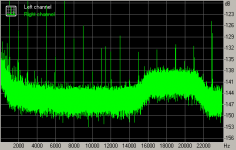
The left channel is relatively free of the 12Khz related trash, so the graphs are pretty ok.
I've found the recorded test tones files give -60dB peak while all the FFT displays seem to show a rms value? It shows lower than -60dB anyway.
I was running 63K in one channel and Y in the other and found that the balance was out and the sound recessed in the channel with the pcm63k. After I swapped out the Y's I found that the A and B points which set operation in the I/V need to be significantly adjust which vastly improved the sound from the 63K's. I hadn't made these adjustments when testing the K's so I expect that their measure performance might be slightly better. I'd also like to retest with the best of the Y's and K's and the I/V operating points correctly set for both types. I suspect that there performance will be much closer than I heard in my listening tests with operating points set correctly for the Y's only.
I've been talking with Spencer about running the DAC single ended so I can listen to pairs. I think this would be very valuable to get a better idea of the individual performance contribution of the various chips.
cheers
Paul
I'd have to go back and check again. Unfortunately I've removed the id stickers from the chips prior to packing to send back to A'af so I'll have to retest to check.
I discovered the right channel of the HDP2 is contributing the 12Khz peak and related harmonics. I have a feeling this is due to a MAX regulator chip. I'm in two minds about fixing this as the recorder was modified by Oade Brothers to their "Super Mod" standard and is sealed with a Oade anti-tamper sticker. I would have to ship back to the US for repairs to retain any kind of Oade warranty. The DIYer in me says "crack it open".
The left channel is relatively free of the 12Khz related trash, so the graphs are pretty ok.
I've found the recorded test tones files give -60dB peak while all the FFT displays seem to show a rms value? It shows lower than -60dB anyway.
I was running 63K in one channel and Y in the other and found that the balance was out and the sound recessed in the channel with the pcm63k. After I swapped out the Y's I found that the A and B points which set operation in the I/V need to be significantly adjust which vastly improved the sound from the 63K's. I hadn't made these adjustments when testing the K's so I expect that their measure performance might be slightly better. I'd also like to retest with the best of the Y's and K's and the I/V operating points correctly set for both types. I suspect that there performance will be much closer than I heard in my listening tests with operating points set correctly for the Y's only.
I've been talking with Spencer about running the DAC single ended so I can listen to pairs. I think this would be very valuable to get a better idea of the individual performance contribution of the various chips.
cheers
Paul
Paul,
Once the Point A and B voltages are set, it is my expectation that no more adjustment is required due to swap of PCM63 chips. I have confirmed that by testing more than 20 chips and yet to find one PCM63 need adjustment again. In most case the point B may drift by 5mV which is not important to the operation of the DAC. Note that the Bi Polar Zero of PCM63 will set the output voltage to GND.
If the voltages drift, there is a possibility that the Jfet IV is oscillating at high frequency at about 96 to 98MHz. The fix has been stated in the assembly manual. Also I have said in another thread that using Black Gate 10uF 50V Non Polar capacitor will solve this issue at all (or any similar shielded body E-cap).
If I know there is no oscillation and voltage changes substantially after changing the chip, then I shall suspect the chips has problem. Especially the dc drift at the input of the Jfet IV.
Spencer
Hi Spencer,
This was a consistent difference across all chips. I set operating points with the Y's then after I swapped back the PCM63K the point b's were all at -7mv and Point A at 8.75V for all chips. Point B is not drifting more that +/-1mv once set, and point A drifts perhaps +/-5mV. All your precautions are in place too - output caps are wrapped in copper foil and tied to ground.
Having point A set 0.25V low seems to have a dramatic, negative effect on sound quality. I suspect you are right but I think I need to find a known good PCM63 as a baseline before I can decide which set of chips is causing this offset.
cheers
Paul
Attachments
I thought I should report that A'af has very kindly offered to send out some chips. 😎
I really appreciate A'af making this offer because the "good" chips he supplied do sound very nice in the D1V3 and I'll be more than happy if all four chips perform to a similar level. 😀
Thanks A'af!!
cheers
Paul
I really appreciate A'af making this offer because the "good" chips he supplied do sound very nice in the D1V3 and I'll be more than happy if all four chips perform to a similar level. 😀
Thanks A'af!!
cheers
Paul
Ongoing
Paul, these are the best news of the day so far & I am happy not to having mislead you about him (A'AF) 🙂 I also remember you wanted to go on a vacation this Friday. Hope you can enjoy it now!
I will try to forget that the only CONSTANT EVIDENCE being yet found on this thread (at least until now) is that MOST OF THE OSCILLOSCOPES here seemed to be UNSOCIABLE, not only towards the PCMs and EACH OTHER, but mainly - toward their OWNERS
Personally, I will be waiting until the Robots will take over 😉 They will also listen to music 😎 ! But Robots are not so far yet, so I shell buy now an Oscilloscope, just not to be left out.
Something to think about (but please NOT during the vacation!!): One is much responsible for the unneeded aggravation he is going through .
.
Yours,
IY
spzzzzkt said:I thought I should report that A'af has very kindly offered to send out some chips.
I really appreciate A'af making this offer…
Paul, these are the best news of the day so far & I am happy not to having mislead you about him (A'AF) 🙂 I also remember you wanted to go on a vacation this Friday. Hope you can enjoy it now!
I will try to forget that the only CONSTANT EVIDENCE being yet found on this thread (at least until now) is that MOST OF THE OSCILLOSCOPES here seemed to be UNSOCIABLE, not only towards the PCMs and EACH OTHER, but mainly - toward their OWNERS
Personally, I will be waiting until the Robots will take over 😉 They will also listen to music 😎 ! But Robots are not so far yet, so I shell buy now an Oscilloscope, just not to be left out.
Something to think about (but please NOT during the vacation!!): One is much responsible for the unneeded aggravation he is going through
.Yours,
IY
Bernhard said:
Bernhard,
I can't log into this. Is the LINK still OK?
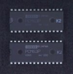
Now that looks a little bit strange to me because K2 should be a stamp, also the whole marking looks a little... I had K2 and it was a stamp. I am saying nothing...
http://imajr.com/Original.aspx?Id=PCM63P-K2_edit_516593
That link should work
http://imajr.com/Original.aspx?Id=PCM63P-K2_edit_516593
That link should work
Indeed
It is as strange as my "Y" - the same kind of print, where the "PCM63" and "BB" are not perfectly one under the other, as it is usually the case with all the "normal" PCMs by BB Japan.
One can see this clearly when comparing to your old K2 Chips, even if they were not from the same bunch 😉
It is as strange as my "Y" - the same kind of print, where the "PCM63" and "BB" are not perfectly one under the other, as it is usually the case with all the "normal" PCMs by BB Japan.
One can see this clearly when comparing to your old K2 Chips, even if they were not from the same bunch 😉
Attachments
JK, IY and All,
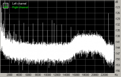
I think the perhaps the harmonic distortion is only part of the story. The pair of the 63K that measure only slightly worse in terms on hd were audibly inferior to the Y that were worse on the basis of harmonics. The impression was of a veil over the sound coming from the channel they were installed in and the result was quite unpleasant to listen too. The DAC sounds ok with all 63K install or all Y's install but the mix and match is not pleasant to listen to due to the mis-matched sound.
Looking closer at the files I made, I summed the best two of each grade in an editor to get an idea of the effect of running in balanced mode. I found that the K's had a broader noise floor than the Y's. It looks like the noise floor could be around 2-3dB higher than the Y's, despite having generally lower peaks on harmonics. Given the listening tests showing the K's to be somewhat veiled it seems the noise floor have significant impact on perceived performance - possibly more so than harmonic distortion.
Wayne at Pass Labs said that he had a rig attached to an Audio Precision digital two which tested for distortion and linearity. The D1 chips were then matched on the basis of these tests. So seems to me that Harmonic Distortion is just a part of the equation and not the whole story.
attached is the spectrum of the summed Y's
Attachments
IY,
you don't actually use a scope for these kind of tests. A good quality sound card and a copy of RMAA or similar analysis software would give you the kind of information Joseph K and I are posting. A good spectrum analyzer such Bernhard uses would be nice but is not essential. The ultimate for these sort of tests would be a Audio Precision unit which can run a whole range of automated tests that would give a better picture of performance than simply looking at spectrums alone.
And I'm not sure I would trust the robots entirely. Without listening to the chips I can't see how I's be able to related what I'm seeing to performance. I'm surprised at just how audible the low level noise is to the overall performance.
cheers
Paul
Came across this interesting article whilst searching for information on DAC linearity testing..
http://www.hit.bme.hu/~papay/edu/DSP/inl.htm
This suggests that there is a direct correlation between Harmonic Distortion and non-linearity.
Also useful information on the parent page...
http://www.hit.bme.hu/~papay/edu/ABCsoup.htm
I hadn't seen the THD + N formula before so it makes a bit more sense that it incorporates a number (6,9?) of the harmonics and the noise floor.
So I suppose the ideal is chip both low noise floor and low harmonic distortion. The Y's definitely meet the low noise floor criteria, and with some selection it should be possible to find a set with low harmonic distortion.
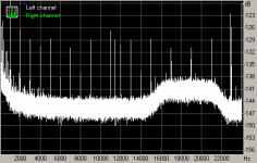
One more pic... this is the spectrum of the two lower performing Y's summed as in the last two.
Noise floor is clearly worse that the best of the Y's I have, and slightly better than best K's. Harmonic Distortion appears to be higher than the best two K's.
I'll do some more tests at with -40dB and 0dB test tones when I get back.
Noise floor is clearly worse that the best of the Y's I have, and slightly better than best K's. Harmonic Distortion appears to be higher than the best two K's.
I'll do some more tests at with -40dB and 0dB test tones when I get back.
Attachments
implementation of the PCM63
Quote
By the way, your Left Channel measurements 991Hz to 20KHz doesn’t look worth then the excellent Tent DAC scoped picture, includes the 3K and 6-7K areas. Moreover, if I am not wrong, the measurements here are much depended & corresponding to the implementation in the D1V3, CD transport, etc (or do I understand this wrong?).
Unquote
I also own TentLabs DAC's (see my web site www.by-rutgers.nl) and I know that the clock's as well as the data are 're-clocked' just before they enter the PCM63.
This makes such a great difference in sound quality that I start to wonder if the most nice measuring PCM63 WITHOUT this reclocking can outperform the TentDac-with a PCM63P at all.....
In other words, I think the implementation of the PCM63 is very important.

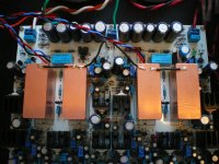
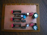
A clarification - I am running my D1V3 with a Tent vxco in a slightly modified version of the original Pass D1 secondary PLL circuit. This makes a very distinct difference in performance of the DAC. The bass and imaging is much tighter and precise than when running from the recovered clock as in the standard D1V3.
Attached is pic of the clock board during construction...
Attached is pic of the clock board during construction...
Attachments
implementation of PCM63
LS,
I'm not sure if I am understood by everybody. For all security I add two schemes which form the end of the TentDac end which I have built in a Philips CD624.
The reclocking I'm talking about has been done with U3 end U3a. U5 end U4 supply the stopped clock for the PCM63 in the next scheme.
I leave out all the details of the power supply etc.
Herb.
ESL + MFB = the best of 2 worlds.
Attachments
- Status
- Not open for further replies.
- Home
- Source & Line
- Digital Line Level
- Real or fake PCM63?