Great news: the testing of the 1st article went smoothly. Everything works as expected. Full production begins and shipment will go out from China to me this Monday. I will test each unit before shipping them out to the GB participants.
Hi, just to make sure this old brain of mine is working (or not) will this work with the original boards. I think it is what you have described in your reply to me. Also, would it hurt to use a smaller pF cap - say 22pF for even quicker shut down?
Thanks Keith
Thanks Keith
Attachments
22pF is an RF filter cap! It won’t smooth 120Hz rectifier bridge ripple much.
The SSRs need about 20mA and you can do the math to see how long a 10uF or 22uF cap charged with the secondaries will provide at least 18vdc. Below that, and circa 5vdc or so, the SSR shuts down. We ran simulations and found that about 22uF gives enough ripple smoothing and shuts down quickly. Try 10uF or 4.7uF and see if it works. If it’s too low you might hear the 120Hz modulation in the SSR.
The SSRs need about 20mA and you can do the math to see how long a 10uF or 22uF cap charged with the secondaries will provide at least 18vdc. Below that, and circa 5vdc or so, the SSR shuts down. We ran simulations and found that about 22uF gives enough ripple smoothing and shuts down quickly. Try 10uF or 4.7uF and see if it works. If it’s too low you might hear the 120Hz modulation in the SSR.
Sorry a typo I did mean 22uF, but my main question was, with this simple psu, will it work correctly and switch off speakers if there is a DC fault in the output even if I'm using just one winding?
Last edited:
Yes. The DC fault is independent of what you are using to power it. The DC is detected by an optoisolator. It’s isolated from the supply voltage. The supply voltage using the small 22uF cap will shut the SSR off in about 100milli seconds.
You only need about 2mA for LED. 20mA will fry it.
So for say 50v supply, use circa 22k to 25k resistor.
You only need about 2mA for LED. 20mA will fry it.
So for say 50v supply, use circa 22k to 25k resistor.
Last edited:
Hi,
The spec for this Halo LED incorporated in a switch is 12v at 19 ma. Just checked the current, and it does draw exactly 19ma. So are you saying then that I could use a separate dc power supply independent from the amp supply and the boards will function as normal. Please bear in mind that I am talking about the first version of the boards and not the latest one that you are currently offering.
The spec for this Halo LED incorporated in a switch is 12v at 19 ma. Just checked the current, and it does draw exactly 19ma. So are you saying then that I could use a separate dc power supply independent from the amp supply and the boards will function as normal. Please bear in mind that I am talking about the first version of the boards and not the latest one that you are currently offering.
Last edited:
Oh, this is to light up your on/off LED front panel switch. Ok. If it’s set up for 20mA that’s fine. You will be drawing 20mA more from your SSR Gen 1. Gen2 is probably about the same. I have not measured yet. So the small capacitance PSU needs to supply 20mA to LED along with 20mA for SSR. 22uF should be fine.
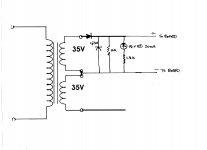
Won't Keith's circuit pick up one half of the power sine wave only?
From the Instant Shutdown Mod circuit sketch, two rectified voltage feeds are shown for a centre tapped secondary. So, is losing half a power cycle OK for operating stability of the SSR?
Wouldn't it be more reliable to simply add in the extra diode? Or have I got my wires crossed?
From the Instant Shutdown Mod circuit sketch, two rectified voltage feeds are shown for a centre tapped secondary. So, is losing half a power cycle OK for operating stability of the SSR?
Wouldn't it be more reliable to simply add in the extra diode? Or have I got my wires crossed?
That's why I was querying whether my circuit would actually work - for me, it was just about halving the supply voltage to the board, using both windings would put the voltage close to the max operating voltage of the board.
I only used 1 winding. You only need 18v or more. More just dissipates more heat on voltage regulator.
Yes, I would add another diode for a full wave wave bridge of using both windings.
These were the schematics by Jhofland earlier in this thread:
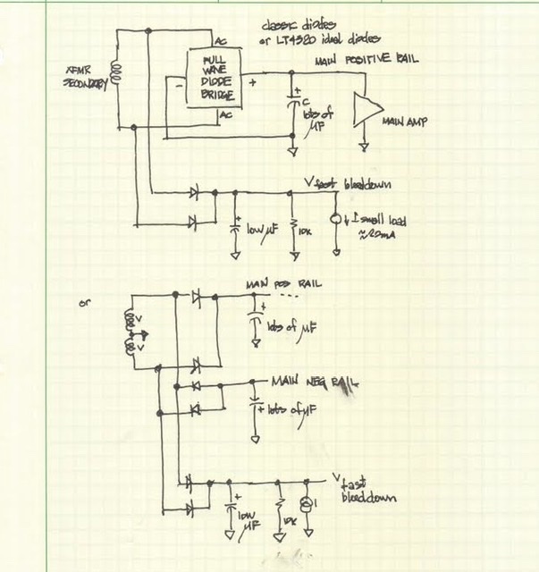
These were the schematics by Jhofland earlier in this thread:
Last edited:
Hi X, just a quick question for you on the first generation SSR boards. I am going to use 2 of them in a Stasis build with +/- 40VDC rails - I assume that the +40VDC / 0V from the amp rail is OK to feed the SSR board? Also what is the maximum DC supply voltage the SSR has been designed for, out of interest?
Correction. The DC supply for Gen1 and Gen2 is limited by the max voltage the on board regulator can handle. That’s got a 150v rating. The MOSFETs for the SSR are rated 100v for Gen 1 and 150v for gen 2.
Running at 150v supply may not be the wisest thing as it draws 20mA x 150v is 3W. That little regulator will be smoking hot. Most amps capable of 150vpp will have rails in the +/-75 to 80v range. And at 80v rails that is 1.6W dissipation. Still a lot but it won’t melt. So really you should not use more the 80v dc. Sorry for the wrong info earlier.
Running at 150v supply may not be the wisest thing as it draws 20mA x 150v is 3W. That little regulator will be smoking hot. Most amps capable of 150vpp will have rails in the +/-75 to 80v range. And at 80v rails that is 1.6W dissipation. Still a lot but it won’t melt. So really you should not use more the 80v dc. Sorry for the wrong info earlier.
Thanks for the 2 replies X, as I am only running at +40VDC, the onboard regulator will only be running at 0.8 watts. None of the amps that I will use my SSR's on will have high rail voltages - so all is OK.
Hi Folks,
I just got word that the new Gen2 SSR’s just shipped from the factory. I should have them in hand in a few days. Once the new boards are received, the $47 pre-order price will increase to $55ea. If you are interested in getting them at the lower price, please order soon.
I just got word that the new Gen2 SSR’s just shipped from the factory. I should have them in hand in a few days. Once the new boards are received, the $47 pre-order price will increase to $55ea. If you are interested in getting them at the lower price, please order soon.
Hi again X, have you got a simple block diagram / wiring diagram for the new Gen 2 SSR pcb as it is to be wired into an amp. I notice one change from the original SSR is that the loudspeaker GND connection now goes to the board - where it didn't in the first version.
I have not found a diagram in the thread, but may have missed it, thanks.
I have not found a diagram in the thread, but may have missed it, thanks.
- Home
- Group Buys
- Ready-to-Run (RTR) SSR DC Speaker Protection and Delay GB