Volly said:Best amp (pre&headphone).
Is it a finished preamp or a work in progress?
I am not able to get the AD815 chip with the SIP mounting here. Only the 24pin SOIC Surface mount type is available. How would one implement this into Carlos's circuit? Please help...
safetyman said:I am not able to get the AD815 chip with the SIP mounting here. Only the 24pin SOIC Surface mount type is available. How would one implement this into Carlos's circuit? Please help...
Hi safetyman,
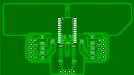
This is how I did it:
http://free.hostdepartment.com/j/jrexton/pre1.jpg
http://free.hostdepartment.com/j/jrexton/preampheat2.jpg
http://free.hostdepartment.com/j/jrexton/
You don't need a PCB, just a steady hand and fine tip on your soldering iron.
Cheers

earsandeyes said:Juma,
I can't see your solution. It is a restricted place?!
E&E
Hi,
No it is not restricted. Try to copy & paste url, or to type it into new browser window:
http://free.hostdepartment.com/j/jrexton/
cheers
rudi said:
Rudi, thanks for being so ready to assist. I saw your project and it gave me goose pimples. 😀 Nah, I don't think I am ready for that yet. I am going to try and get the AD815 SIP chips from B.G. Micros and implement Carlos's design. Looks more achievable for me. 😀
juma said:
Hi safetyman,
This is how I did it:
http://free.hostdepartment.com/j/jrexton/pre1.jpg
http://free.hostdepartment.com/j/jrexton/preampheat2.jpg
http://free.hostdepartment.com/j/jrexton/
You don't need a PCB, just a steady hand and fine tip on your soldering iron.
Cheers
Juma, thanks for the assist too. Really nice. Maybe one day, I'll learn enough to build something as nice as what you have done. 🙂
Carlos, any chance of a pic of the underside of your preamp. Stupid question? Probably is.😀 Just that I am going to try to build it like you did with the stickboard and the pics are going to be my kinda reference.
safetyman said:
Rudi, thanks for being so ready to assist. I saw your project and it gave me goose pimples. 😀 Nah, I don't think I am ready for that yet. I am going to try and get the AD815 SIP chips from B.G. Micros and implement Carlos's design. Looks more achievable for me. 😀
Hi safetyman. Up until two weeks ago I were a bit sceptical whether or not I can make my own PC board. It took me a day or so to get the technique right now it takes me 3 hours to make the PCB and build it and have it playing. And soldering SMD’s are really very simple
I am testing various DC servo arrangements now so I have gone through some prototypes already. (But they all sound the same – amazing)
Rudi
What size power supply bypass cap are you using for your dc servo?
Have you increased the value for the resistor,yet?
What size power supply bypass cap are you using for your dc servo?
Have you increased the value for the resistor,yet?
I assume that you talking about the bypass caps on the opamp. I have used 100nf but honestly i don't think you need them. the opamps run on the same power as the AD815, i will have my dual opamp version ready this afternoon. my feeling is that it will be better (not sonicly but electrically) than using two, less strain on the PSU
i have used a value of 820k with a 1uf film cap for the DC servo and it sounded worse, loss of clarity but only marginal. the values suggested works the best. The guy that designed it for me does this everyday for a living and he had very good reason for using those values.
i have used a value of 820k with a 1uf film cap for the DC servo and it sounded worse, loss of clarity but only marginal. the values suggested works the best. The guy that designed it for me does this everyday for a living and he had very good reason for using those values.
Thanks for the reply
The 820K resistor was for R7 right?
With the value in your schematics(servo) the servo is set at .2Hz and below?
If I use a 174k resistor and a 3.5uf cap,do I change R9 or is R9 just a load for the output of the op amp?
How was the value for the resistors calculated?
The 820K resistor was for R7 right?
With the value in your schematics(servo) the servo is set at .2Hz and below?
If I use a 174k resistor and a 3.5uf cap,do I change R9 or is R9 just a load for the output of the op amp?
How was the value for the resistors calculated?
rudi, how did you mount the heatsink on to the AD815 chip? BTW, which version of the LM317 and LM337 is the correct one. There seems to be many, with different letters behind them? 
rudi, thanks for the encouragement... how the hell am I going to attempt what you did when I don't even know what is a DC servo? 😀 When I can get someone to help me make boards, I am going to try your X-Caliber... that's for sure. 😉
rudi, thanks for the encouragement... how the hell am I going to attempt what you did when I don't even know what is a DC servo? 😀 When I can get someone to help me make boards, I am going to try your X-Caliber... that's for sure. 😉
Leave the 10K as is. what you can do is times my values by 10 so you can use 330K and 4.7uf then you would be closer to our calcs. if you in the region of 1hz youre OK
HI Carlos
I am still using the OPA627 but the OPA134 works great aswell. I am building one with a OPA2134 at the moment
I am still using the OPA627 but the OPA134 works great aswell. I am building one with a OPA2134 at the moment
- Status
- Not open for further replies.
- Home
- Amplifiers
- Chip Amps
- (re)searching for a better preamp