Rudi, I had initially considered a DC servo, that's an option, although it can have some impact on the performance.
Your situation is different, as you are not using a volume pot, and my DC null circuit was optimized for this. It will not work 100% in your case.
My DC null circuit also eliminates the input DC-offset of this chip, which is on the high side and problematic for a volume pot. This is not a problem for you.
Tell me, how much DC do you measure on the input of the pre?
Just checking. With a gain of one there is no gain to give away. Is it similar to the servo in the AN-1192 schematics(less the diodes)?
Hi Carlos
i have just spoken to my friend and the proper name is a proportional integrator control (PI).
I have 0V on the input.
the performance with this is actually better than with the caps. it does not sit in the signal path . it just measures from the signal path. (but that we know could also have a influence. but my overall experience is that it is much better than before
Attachments
rudi said:the performance with this is actually better than with the caps.
Naturally.
rudi said:it does not sit in the signal path .
It does.
And if you try several op-amps you will have different performance.
Btw I think those resistors should have higher values.
Hi Carlos
it works fine as is. what values would you recommend.
i have tried several opamps and to be honest it did not do anything noticable.
but in all fairness I am using a OPA627 but that i just because I have plenty of them 😀
it works fine as is. what values would you recommend.
i have tried several opamps and to be honest it did not do anything noticable.
but in all fairness I am using a OPA627 but that i just because I have plenty of them 😀
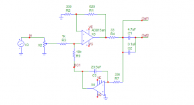
rudi said:4 resistors. 4 small 47uf caps and two opamps. (or one dual) and some bridges (links)
The 4 caps and 4 resistor gets split two for each channel right?
I dont see the second cap is your schematics.
Why the 23.5uf cap instead of the 47uf?
connect two 47uf electro caps in a bipolar configuration + with + and the two - into the circuit. then you have 23.5uf
rudi said:connect two 47uf electro caps in a bipolar configuration + with + and the two - into the circuit. then you have 23.5uf
Hundreds of K, up to 1M.
Then, the cap could be much smaller, film.
Oh well, one way or the other. It works really well and it is a very simple circuit that you never have to worry about or have to adjust. I would be interested hear your opinion once you used it and maybe come up with some alternative values.
For those that wants to try this circuit
One thing that is important is that you choose an opamp with a very low dc offset. A good starting point is a 5534
For those that wants to try this circuit
One thing that is important is that you choose an opamp with a very low dc offset. A good starting point is a 5534
rudi said:One thing that is important is that you choose an opamp with a very low dc offset. A good starting point is a 5534
Rudi, you should use a fet input op-amp.
For something like this pre, I would consider using a pair of OPA627s. 😎
Or at least an OPA2132/4.
I may give it a try, sooner or later.
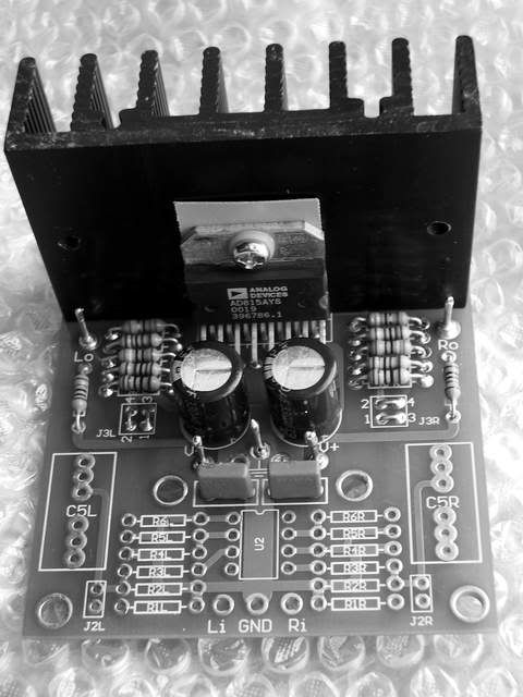
I just finished the 815 pre.
The amp is direct coupling, 1V/2V setting, power with a dual 15V supply and match all the resistors on both channels. offset stay stably on 1.2mV(L)/7.6mV(R).
I'm truly satisfly with its wonderful sound.
Thank Carlos for his introduce this fantastic Pre/Head amp.
The amp is direct coupling, 1V/2V setting, power with a dual 15V supply and match all the resistors on both channels. offset stay stably on 1.2mV(L)/7.6mV(R).
I'm truly satisfly with its wonderful sound.
Thank Carlos for his introduce this fantastic Pre/Head amp.
Very nice work.
Does it have the same offset at all potentiometer positions and when the chip temperate inceases?
Is you Null circuit off board?
Does it have the same offset at all potentiometer positions and when the chip temperate inceases?
Is you Null circuit off board?
hi, jaudio
I don't use the Null circuit, and the offset will drift 1mV more when the potentiometer fully turn clockwise.
I don't use the Null circuit, and the offset will drift 1mV more when the potentiometer fully turn clockwise.
Re: I just finished the 815 pre.
Hi YLS
did you use the exact resistor values as Carlos suggested because the figure you getting is truely impressive
YLS said:The amp is direct coupling, 1V/2V setting, power with a dual 15V supply and match all the resistors on both channels. offset stay stably on 1.2mV(L)/7.6mV(R).
[
Hi YLS
did you use the exact resistor values as Carlos suggested because the figure you getting is truely impressive
To get those DC values the input resistor to ground must be very small, which is a tough load for the previous stage (+ volume pot).
Also, the signal will be attenuated and you must use more gain on the chip.

Anyway, 7.6mv still doesn't leave you a choice: you must use an input coupling cap on the power amp (or on the output of the pre).
If the power amp has a gain of 20, 7.6 x 20 = 152mv, and more the dc of the power amp.
Also, the signal will be attenuated and you must use more gain on the chip.
Anyway, 7.6mv still doesn't leave you a choice: you must use an input coupling cap on the power amp (or on the output of the pre).
If the power amp has a gain of 20, 7.6 x 20 = 152mv, and more the dc of the power amp.
Hi YLS,
Great picture, nice board, interesting layout.
Would you be so kind and post a schematic? I am interested in seeing how you achieved such low offset. Thanks much. 🙂
Bruce
Great picture, nice board, interesting layout.
Would you be so kind and post a schematic? I am interested in seeing how you achieved such low offset. Thanks much. 🙂
Bruce
Hi all,
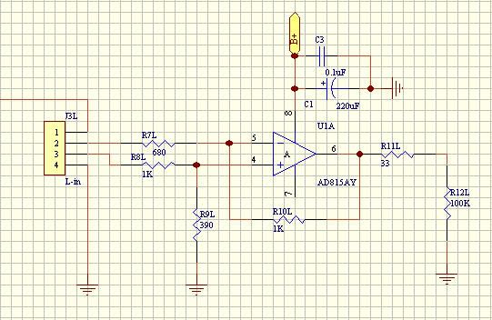
I use to match the (DC) resistance to both inputs, the DC values of the + input resistor neet to scale down.
this is the schematic, the NI input resistor (R9) = R7//R10.
just as Carlos said, which is a bit tough to the previous stage, so on the PCB, an extra gain-stage/buffer-stage was reserved.
I use to match the (DC) resistance to both inputs, the DC values of the + input resistor neet to scale down.
this is the schematic, the NI input resistor (R9) = R7//R10.
just as Carlos said, which is a bit tough to the previous stage, so on the PCB, an extra gain-stage/buffer-stage was reserved.
YLS said:Hi all,
I use to match the (DC) resistance to both inputs, the DC values of the + input resistor neet to scale down.
this is the schematic, the NI input resistor (R9) = R7//R10.
just as Carlos said, which is a bit tough to the previous stage, so on the PCB, an extra gain-stage/buffer-stage was reserved.
Yes, YLS, I also started matching impedances and offset was very low, but it's useless, as you have a very limited range of feedback resistor values you can use.
The signal is also attenuated, so you must use more gain, and again you are limited.
An input buffer was out of the question for me.
- Status
- Not open for further replies.
- Home
- Amplifiers
- Chip Amps
- (re)searching for a better preamp