Radian spec (198cm2) seems in the right ballpark to meT/S parameters: Sd doesn't look correct from either sources. Can someone post the correct diameter (or area) of the diaphragm

Thanks. They had it as 19.800m sqM what is wrong.
198 cm2 = 0.0198 sqM = 19800 mm2
Must be the imperial to metric solving method. Haha.
198 cm2 = 0.0198 sqM = 19800 mm2
Must be the imperial to metric solving method. Haha.
I did think that was odd but it makes sense if the m is m for milli ... i.e. 19.800m would then by 19.8/1000 = 0.0198Thanks. They had it as 19.800m sqM what is wrong.
198 cm2 = 0.0198 sqM = 19800 mm2
Must be the imperial to metric solving method. Haha.
quite a bizarre way to write it admittedly!

The xover results in post #52 using 3||3dood's data did not account for z-offset between LF and HF, and with a 15 deg tilt downwards (rear surround placement).
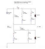
So . . . the xover was revised with z-offset at 8.7 mm (per PM with 3||3d00d), and y-tilt at -15 deg. The files used were again from the "5208c_xo_design.zip" file on Post #14.
In the xover on this post, the dc resistance for each coil (ri) is listed with the inductance value. These values came from a P.E. catalog for 18 ga air core coils. The resistor shown immediately after each coil (if present) is a separate component.
The crossover point is close to 2 kHz. I looked at 1.5 kHz, but the larger inductor value increased the impedance peak at 5 kHz to around 50 ohms. These values keep it down to about 20 ohms. Hopefully this xover might be a good starting point.
Oh, and Merry Christmas to all!
Attachments
Last edited:
nice work, thanks!
I've been dabbling with trying for a higher XO point this week but was struggling to handle the breakup of the woofer without impedance crashing really low. You look like you've handled that nicely though. I will build this xo in the new year to try it out.
I've been dabbling with trying for a higher XO point this week but was struggling to handle the breakup of the woofer without impedance crashing really low. You look like you've handled that nicely though. I will build this xo in the new year to try it out.
nice work, thanks!
I've been dabbling with trying for a higher XO point this week but was struggling to handle the breakup of the woofer without impedance crashing really low. You look like you've handled that nicely though. I will build this xo in the new year to try it out.
Dave has done a lot of award winning crossovers here in the Pacific Northwest. He was a Math Teacher before he changed direction and went back to school to earn a degree as an Engineer. Dave has since earned several advanced degrees in Mathematics and Engineering. He works at some sort of airplane factory near Seattle.
Best Regards,
TerryO
nice work, thanks!
I've been dabbling with trying for a higher XO point this week but was struggling to handle the breakup of the woofer without impedance crashing really low. You look like you've handled that nicely though. I will build this xo in the new year to try it out.
Hope it all works well. Keep us posted.
Hello Dave R.,
I notice you do not seem to fully compensate the Baffle step, but chose a somewhat shelving 150 Hz -1 kHz.
May I be so bold as to ask what your reason is for designing a non-flat 100-1000 Hz region?
Thank you,
Kind regards,
Eelco de Bode
I notice you do not seem to fully compensate the Baffle step, but chose a somewhat shelving 150 Hz -1 kHz.
May I be so bold as to ask what your reason is for designing a non-flat 100-1000 Hz region?
Thank you,
Kind regards,
Eelco de Bode
Hello Dave R.,
I notice you do not seem to fully compensate the Baffle step, but chose a somewhat shelving 150 Hz -1 kHz.
May I be so bold as to ask what your reason is for designing a non-flat 100-1000 Hz region?
Thank you,
Kind regards,
Eelco de Bode
The form of the non-flat region from 100-1000 hz is not intentional (just a consequence of looking for good balance of trade-offs between spl, impedance, phase, transfer function, etc).
As a surround speaker with off-axis placement, and with subwoofer assistance this is probably a good starting point.
Hi All,
I'm going to have to start moving on this project. For anyone interested, I'm quite pleased with the smooth transition Dave's crossover has created. It's very natural and relaxed without a hint of the change-over from one driver to the other. All I can say is this OB setup, with these drivers and Dave's crossover really sounds quite nice in my system.
Best Regards,
TerryO
FWIW I came up with a new set of filters that provide a similar response through the crossover to Dave R's, the only difference (in FR terms) being that mine aims for a flatter response to a lower frequency (it starts to roll off around 180-200Hz but is largely flat above that point). It looks like an LR4 at ~2kHz on paper basically.
This is much improved to my previous filter (pretty much an LR6 at 1600Hz), the harshness I had previously is gone and it really works much better. I definitely recommend that sort of crossover shape for this driver, thanks to Dave R for pointing me in that direction.
This is much improved to my previous filter (pretty much an LR6 at 1600Hz), the harshness I had previously is gone and it really works much better. I definitely recommend that sort of crossover shape for this driver, thanks to Dave R for pointing me in that direction.

I played my speakers a couple of weeks back for the members of the "Sound DIY Club". This was done with "H" frame enclosed 18 inch woofers powered by a couple of plate amps that Dave had. With a bit of adjustment they sounded quite good (I thought) and evidently the members thought so as well. With our quick and dirty adjustment routine it sounded good enough to continue the listening session...which, with my speakers, is not always the case. 😉
Best Regards,
TerryO
Best Regards,
TerryO
Wondering if Terry is still using his Radian 5208C based OB speakers, and also, if there have have any updates since (crossover, Beryllium tweeter etc.)? I'm highly impressed with the smooth acoustic phase handover.
Greetings from Switzerland, David.
Greetings from Switzerland, David.
Wondering if Terry is still using his Radian 5208C based OB speakers, and also, if there have have any updates since (crossover, Beryllium tweeter etc.)? I'm highly impressed with the smooth acoustic phase handover.
Greetings from Switzerland, David.
Hello David,
Yes, TerryO's 18-inch H-frames are now integrated with his Radian 5208c co-ax drivers. The series crossover that was made for the co-ax units was retained, and the H-frames are hooked up in parallel to that. Crossovers are passive.
The finished speakers (now 3-ways) were presented and auditioned at our local diy audio club last Saturday. Happy to say there were a lot of positive comments. 🙂 They sound "natural", with very seamless transitions between drivers through the crossover regions. No harshness or resonances were noticed. It sounds good on-axis and off-axis. And of course, the 18-inchers really give it a full sound with realistic drum and bass.
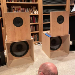
Attached is a picture of the finished mountings.
The 18" H-frame is 24"W x 23.5"H x 24"D, with baffle half-way back.
Co-ax unit is open baffle 20"W x 24"H, with driver center located 16" above its base. The center of Co-ax is 39.5"H above the floor. The Co-ax baffle is located directly over the opening of the H-frame.
I'll gather up some info and post it later.
Attachments
Last edited:
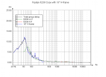
TerryO's Radian 5208c OB with 18" H-frame
The comments below refer to the attached graphs from the crossover work that was done. LspCad was used for the simulations.
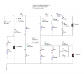
Schematic:
The Coax unit has a series crossover (3rd order electrical on both hi and lo frequency drivers)
The 18" H-frame was added in parallel to all of that (2nd order).
A 133 uF cap was added in line with the Co-ax unit for lower crossover. at 170 Hz.
The notch filter (R7, L6, C6) on the Hi F driver attenuates the spl at the top end from 4-20 kHz.
The notch (L10, R13, C10) on the Lo F driver attenuates an spl resonance around 900 Hz.
The notch (R11, L8, C7) across the coax attenuates a 20-ohm impedance peak at 4 kHz.
Resistors were added in particular places to improve phase alignment, impedance, or SPL.
Standard components (and combinations) were used. Measured values of components are shown. Left and Right crossovers are matched to within
½% or less, where possible.
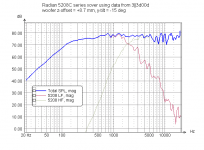
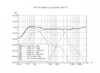
SPL:
The SPL graph shows the (raw) unfiltered and the filtered drivers, as well as the total summed response.
The dotted and dashed lines show raw measured data. Solid lines are filtered.
The lower crossover frequency is at 170 Hz, and the upper is centered at 2200 Hz.
The dip in the response is around 3 or 4 dB.
The 18" bass unit is 4 or 5 dB above the dip, and 190 Hz was targeted as the midpoint frequency of the transition to the dip. This corresponds to a baffle step for the 24" baffle width.
The 3 or 4 dB boost in high frequency was targeted at 17 kHz and above.
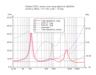
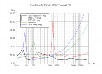
Impedance:
Above 1 kHz, the impedance is between 4 and 6 ohms.
Minimum impedance is 4 ohms.
The maximum impedance is less than 20 ohms.
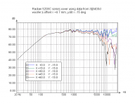
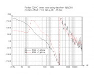
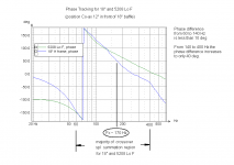
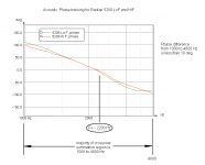
Acoustic (SPL) Phase:
In the lower crossover region (60-400 Hz), the phase tracking is excellent below 140 Hz, and still quite acceptable from 140-400 Hz.
The tracking in the upper crossover region (1 kHz - 4 kHz) is excellent throughout.
The comments below refer to the attached graphs from the crossover work that was done. LspCad was used for the simulations.
Schematic:
The Coax unit has a series crossover (3rd order electrical on both hi and lo frequency drivers)
The 18" H-frame was added in parallel to all of that (2nd order).
A 133 uF cap was added in line with the Co-ax unit for lower crossover. at 170 Hz.
The notch filter (R7, L6, C6) on the Hi F driver attenuates the spl at the top end from 4-20 kHz.
The notch (L10, R13, C10) on the Lo F driver attenuates an spl resonance around 900 Hz.
The notch (R11, L8, C7) across the coax attenuates a 20-ohm impedance peak at 4 kHz.
Resistors were added in particular places to improve phase alignment, impedance, or SPL.
Standard components (and combinations) were used. Measured values of components are shown. Left and Right crossovers are matched to within
½% or less, where possible.
SPL:
The SPL graph shows the (raw) unfiltered and the filtered drivers, as well as the total summed response.
The dotted and dashed lines show raw measured data. Solid lines are filtered.
The lower crossover frequency is at 170 Hz, and the upper is centered at 2200 Hz.
The dip in the response is around 3 or 4 dB.
The 18" bass unit is 4 or 5 dB above the dip, and 190 Hz was targeted as the midpoint frequency of the transition to the dip. This corresponds to a baffle step for the 24" baffle width.
The 3 or 4 dB boost in high frequency was targeted at 17 kHz and above.
Impedance:
Above 1 kHz, the impedance is between 4 and 6 ohms.
Minimum impedance is 4 ohms.
The maximum impedance is less than 20 ohms.
Acoustic (SPL) Phase:
In the lower crossover region (60-400 Hz), the phase tracking is excellent below 140 Hz, and still quite acceptable from 140-400 Hz.
The tracking in the upper crossover region (1 kHz - 4 kHz) is excellent throughout.
Attachments
Last edited:
- Home
- Loudspeakers
- Multi-Way
- Radian 5208c coaxial project