Not 100%, but that's not important - Citizen124032 circuit does not correspond exactly to the SUSY principle.Indeed, the I/O and feedback topology is identical, despite the differing internals.
I don't want to insert Nelson's principle circuit (with the copyright from 2003 and the patent from 1993?!) at this point.
It can be found right at the beginning of the aforementioned thread, which in my opinion was exemplary, 21 years ago.
kind regards,
HBt.
Last edited:
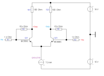
Please explain in detail how the complete interconnection between the nodes q19_base and q18_base works.That cs is ultra stable, and with the rubber zener guarantees bumpless swiching on/off.
Also what or who is thermally coupled to whom.
By the way, do you have enough components to select /and match them exactly and form pairs?
Attachments
Sorry, I didn't mean to make you feel insecure.I'm curious what doesn't match, as regards connections of I/O and feedback.
Quickly, let's take a BJT, simplified representation - and consider C as the output node, then B is the inverting input with respect to C and E is the non-inverting input. If we now look dynamically at the two inputs, we can clearly see different impedances.
Ideally, number 1 would be infinitely large and number 2 infinitely small.
This is the case with the Hiraga (also with the SuSy), but not with the SuperDuper "HeadSea".
In the Hiraga, the resistance ratio Rf/Rn does not determine the resulting bandwidth, in the Hiraga it is completely independent of this. fh is determined here by the size of the negative feedback resistor Rf alone and can therefore also be specifically adjusted.
If I am not mistaken?, but I can of course check this.
Hopefully this (as a pointer) will shed some light on the situation.
The most important fact is that there are four basic types of negative feedback that need to be distinguished.
Don't think too much about it;I'm curious what doesn't match, as regards connections of I/O and feedback.
I have understood you - and I have nothing to criticize or even call incorrect.
{
Compare the singleton as a differential point with the differential amplifier (pair) and also a Norton OP, see also current-feedback.
}
HBt.
No insecurity 🙂 Genuine curiosity as to what I've missed. Always a fine line to walk, stating something with certainty when I know I could have missed something, but it leads to more productive discussion in general--as long as the answer to a challenge is constructive engagement rather than digging one's heels in. I am here to learn and exercise my mind. On that note, I hope @Citizen124032 has not taken any of what I've written as criticism of his design or an attack.
The Hiraga and the Mark McGwire Hiraga certainly have different feedback topologies. I was referring to the SUSY, which appears to me to use the same feedback topology as citizen employs.
The Hiraga and the Mark McGwire Hiraga certainly have different feedback topologies. I was referring to the SUSY, which appears to me to use the same feedback topology as citizen employs.

I already recognized this with your first post in the Eisenport thread 🙂.
Citizen124032's idea doesn't really have anything in common with J.H. Design, anymore and unfortunately the circuit doesn't fulfill the criteria of the N.P. SuSy, but it is definitely a kind of X-Amp. To put it clearly - a bridge amplifier, nothing more and nothing less. I doubt whether it will ever see the light of day in working order.
Have you already considered the "ultra-stable cs"? Or modeled the entire circuit as a control loop?
Let's have a break for now,
HBt.
I was referring to the SUSY, which appears to me to use the same feedback topology as citizen employs.
Citizen124032's idea doesn't really have anything in common with J.H. Design, anymore and unfortunately the circuit doesn't fulfill the criteria of the N.P. SuSy, but it is definitely a kind of X-Amp. To put it clearly - a bridge amplifier, nothing more and nothing less. I doubt whether it will ever see the light of day in working order.
Have you already considered the "ultra-stable cs"? Or modeled the entire circuit as a control loop?
Let's have a break for now,
HBt.
Once distortion gets low enough such that an improvement in the distortion measurement is inaudible, then I see no real reason for striving for a better figure beyond the exercise in engineering needed to achieve that. Why order a drop forge when all you need is a tack hammer?^
That helps, because I myself belong to exactly this group.
100% agreed. Once I designed my VFET monoblock with superdupa technical data - just as an exercise in engineering. On a daily basis I listen to TPA3118🙂
Very wise!100% agreed. Once I designed my VFET monoblock with superdupa technical data - just as an exercise in engineering. On a daily basis I listen to TPA3118
And I think you can also contribute a concrete dimensioning - perhaps a small 5 to 10 watt audio amplifier that at least fulfills the ancient HiFi DIN standard - i.e. is suitable for everyday use and reliable.
Since you mentioned the "old" DIN 45500 norm i ll just point an observation since sometimes the path of a road can be better understood when starting from its end rather than from its beginning.
It makes about sure that there s very few speakers, if any, that are up to even the most miserable amplifier assuming that
it s just a little above this norm, as speakers distorsion is on the order of a few percents, and that s why almost all amplifiers
will sound good enough unless there s a gross misconception in the design.
We can routinely talk of 0.1dB linearity within 20-20KHz, but is everyone sure that his speakers are just within the DIN 45500 norm?
So in a way concentrating the efforts on the amplifier is just constantly reinventing the wheel while never adressing the most rustic part of the vehicule to wich it will be attached, or to use a more vulgar expression to feed a pig with some very refined cuisine.
Attachments
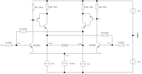
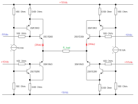
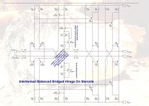
The H-bridge
For a better understanding of what this case is all about, hopefully.
@Citizen124032,
would you like to reveal your SPICE models?
For a better understanding of what this case is all about, hopefully.
@Citizen124032,
would you like to reveal your SPICE models?
Attachments
🤣The Hiraga and the Mark McGwire Hiraga certainly have different feedback topologies.
Mark the baseball star Hiraga
But that was an insider, wasn't it?
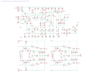
The ultra-stable and magical source / sink
Dear Citizen124032,
are you absolutely sure that your design is actually mature, functional and practical - or is it just a wish, a belief?
I have my doubts. But in the end, the test setup/experiment will bring ultimate clarity.
In any case, I wish you success.
kindly,
HBt.
Dear Citizen124032,
are you absolutely sure that your design is actually mature, functional and practical - or is it just a wish, a belief?
I have my doubts. But in the end, the test setup/experiment will bring ultimate clarity.
In any case, I wish you success.
kindly,
HBt.
Attachments
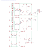
Thank you very much,
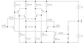
for making your circuit /schematic proposal available to us - as a counterstatement to Eisenport and Cumbbs ideas. At the moment I think it still holds back a lot of potential.
Bye,
HBt.
for making your circuit /schematic proposal available to us - as a counterstatement to Eisenport and Cumbbs ideas. At the moment I think it still holds back a lot of potential.
Bye,
HBt.
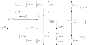
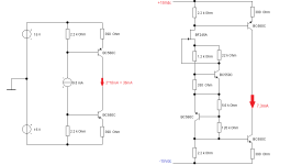
Extrem-A
#
This is a bridge with +/-30Vdc Rails and autobias!
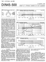
Unfortunately, the entire article requires an infinite amount of tolerance for the written German word.
I hope the translation AI smooths out the gibberish of the German edition.
sqrt(2) * sqrt(50W / 6Ohm) = 4,082A_peak lead to 100W_peak equal to 50W_rms; 50 watts in operating class B, I now consider it a bit far-fetched to deduce 2Adc as a permanent quiescent current. Unless, of course, we calculate the dynamic case a little bit to nicely for the push-pull class A-operation.
Iq =
1/2 * sqrt(2) * (60Wp/8Ohm) = 1/2 * sqrt(4*30Wrms/8Ohm) = sqrt(4)/2 * sqrt(30Wrms/8Ohm) => sqrt(30Wrms/8Ohm) !
So, now we are back to the classic, 1.94Adc (for the 30W HeadSea).
100W(RMS) under a static load of 8Ohm now leads to a quiescent current of 3.54Adc for the ExtremeA - and to 0.184Ohm for the obligatory emitter resistor.
Only the single-ended circuit must carry at least the peak current of the load (expressed as Iq) as quiescent current. For push-pull, it is half this value.
I don't know when the Elektor article on the "ExtremA" audio amplifier was published, but its promised output in Class A mode is said to be a full 100W PowerAmpThe commercial use is not permitted without the express permission of the authors. With questions and general questions about the design can be directed to
the authors at bruno@hypex.nl and ssassen@hardwareanalysis.com.
#
This is a bridge with +/-30Vdc Rails and autobias!
Unfortunately, the entire article requires an infinite amount of tolerance for the written German word.
I hope the translation AI smooths out the gibberish of the German edition.
You can read this under the customization optionsTaking into account the dimensions of the heat sink, the quiescent current can also be adapted to individual requirements.
(2,05A)^2 * 6Ohm = 25,215W_peak equal to 12,61W_rms !For example, if a lower output power is required. As already described, the quiescent current is half the maximum current that can be supplied in class A.
If an output power of 50 watts at 6 ohms is sufficient, the peak output current must be 4.1 A, which requires a quiescent current of 2.05 A.
The quiescent current is determined by the emitter resistors, above which there is a voltage of 0.65 V without an input signal.
For 0.65 V at 2.05 amps, the emitter resistors would theoretically have to be 0.32 ohms. The maximum output voltage is 25 V. To be able to supply this, you need no more than 12.5 V per end transistor, or 14 V in round figures.
Again:Both output stages together now convert 2 x 2.05 A x 2 x 14 V = 115 W into heat.
heat. It is therefore clear that the efficiency of the amplifier is less than 50 %. In addition, a loudspeaker with a nominal impedance of 6 ohms can, under certain circumstances, absorb more current
than an ohmic resistor with the same resistance value. In this case, it seems appropriate to use the class B current reserve for this additional current.
the class B current reserve for this additional current.
sqrt(2) * sqrt(50W / 6Ohm) = 4,082A_peak lead to 100W_peak equal to 50W_rms; 50 watts in operating class B, I now consider it a bit far-fetched to deduce 2Adc as a permanent quiescent current. Unless, of course, we calculate the dynamic case a little bit to nicely for the push-pull class A-operation.
Iq =
1/2 * sqrt(2) * (60Wp/8Ohm) = 1/2 * sqrt(4*30Wrms/8Ohm) = sqrt(4)/2 * sqrt(30Wrms/8Ohm) => sqrt(30Wrms/8Ohm) !
So, now we are back to the classic, 1.94Adc (for the 30W HeadSea).
100W(RMS) under a static load of 8Ohm now leads to a quiescent current of 3.54Adc for the ExtremeA - and to 0.184Ohm for the obligatory emitter resistor.
Only the single-ended circuit must carry at least the peak current of the load (expressed as Iq) as quiescent current. For push-pull, it is half this value.
One last question
Since 'HeadSea' is also a classic push-pull amplifier, Iq_8=1.94A (or Iq_4=2.74A) should be sufficient and this would allow us to reconsider the basic component dimensioning.
Or should the anabolically upgraded amplifier actually be designed for complex loads of less than 4 ohms (under full scale and power) ?
HBt.
Attachments
At the end of a journey, every dazzling bubble bursts, including the so-called draft (the authors' formulation) 'ExtremA' - which nevertheless led to a final amp and an incredibly poorly formulated article.
I suspect that Citizen124032 also knows the article, but I only found it by chance today in a German high-end forum.
Let's summarize:
Class A can mutate into a very demanding challenge - or it can be quite simple.
I suspect that Citizen124032 also knows the article, but I only found it by chance today in a German high-end forum.
Let's summarize:
Class A can mutate into a very demanding challenge - or it can be quite simple.
Attachments
- Home
- Amplifiers
- Solid State
- Questions of faith - reflections on your own taste, thoughts about right or wrong!