Dear Citizen124032,
as soon as you have set up your bridge amplifier (symmetrical between rails) in the real world, it would be great if you would initiate a new thread about it.
Thank you very much for the insights you have given, all the best,
HBt.
as soon as you have set up your bridge amplifier (symmetrical between rails) in the real world, it would be great if you would initiate a new thread about it.
Thank you very much for the insights you have given, all the best,
HBt.
I listen more calmly, but cannot in all seriousness call anything below 10W a "power amp".
Well,
100W or even 1kW wouldn't be a big problem.
But the distinction is also different, namely small signal amplification vs. large signal amplification in the low frequency range.
🙂
This is the only thing the circuit from posting #79 has in common with J.H.'s suggestion.

What the supposedly new circuit, but coincidences exist, is quite similar to (to put it diplomatically) is Mr. Pass' X-Amp.
Just over two decades ago, this type of circuit was all the hype.
At first glance, the drawn illustration with its slightly disturbing (at least to me) background image blurs the fact of the copied SUSY, the "super symmetry".
I can't make out "Jean Hiraga blown up".
The special thing about the Hiraga is not just the symmetry between the rails, but also the type of negative feedback, as well as the jFet-BJT cascode on the le Monstre.
We distinguish between a total of four types of negative feedback.
The big topic of negative feedback is clearly a case for Jan Didden, who probably won't write anything in this thread.
#
I am looking forward to the real implementation and wish you Citizen124032 success with your project - and please don't mislead us any more.
Best regards,
HBt.
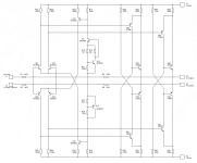
I have taken the liberty of removing everything that blocks the free view and spirit of Citizen124032's new X-Amplifier.
With a concept like this, there are a few challenges that need to be overcome - but I don't want to anticipate anything.
Perhaps the polarizing attitude (Citizen and Cumbb) can spur a new debate on the exciting topic of SUSY. Single-ended and push-pull operation are equally feasible with this concept.
Absolutely nothing new, but still exciting.
Attachments
Well,
100W or even 1kW wouldn't be a big problem.
Using TO-126 in SE with a resistor load? Would love to see this.
Using TO-126 in SE with a resistor load? Would love to see this.
https://en.wikipedia.org/wiki/TO-126
I'm actually the wrong person to ask, because cumbb opened this barrel and not me, but why shouldn't it be possible?
(100VA / 4 V/A )^(1/2) = 5A
So it's a matter of cleverly dividing up 7 amps, which is feasible - but I would only do it in push-pull B mode (for all the old Germans, this is already AB mode).
20 pieces and the store rocks.
😉
https://en.wikipedia.org/wiki/Sziklai_pairThis is the only thing the circuit from posting #79 has in common with J.H.'s suggestion.
https://en.wikipedia.org/wiki/George_Clifford_Sziklai
De-hallmarking, an effort.spirit of Citizen
One notice the absence of e-deg at the input diff's which should be there.
That cs is ultra stable, and with the rubber zener guarantees bumpless swiching on/off.
Inverters are not often seen, let alone bound instumentation front end couples.
Accepts asym and sym signals alike, even unbalanced sym signals, and ease them out symmetrical at the output.
All is running quite hot, for other reasons.
Supply rails at twice value demands extra output legs, but simu's are ok with it.
Another simu is a naked (no ri) ac source at the outputs driving into those output legs; guess.
This circuit was designed for another purpose: getting rid of the marvallous Sziklai's in favor of compound solid state triodes, consisting of two active devices and some resistors only. A collector-collector output alike the V-fet 4650/5650 amplifiers. All has become deep frozen now.
Unfortunately, I can only repeat myself and refer to posting #81.
Incidentally, every complementary symmetrical circuit design (especially with sufficient charging capacity in the power supply unit) starts and stops smoothly - all without a switch-on or switch-off pop.
Incidentally, every complementary symmetrical circuit design (especially with sufficient charging capacity in the power supply unit) starts and stops smoothly - all without a switch-on or switch-off pop.
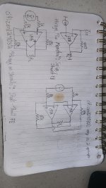
It bears some resemblance to Hiraga, an IPS followed by CFP CE OPS, all symmetrical/complementary, but that's about it.
IPS is different in all respects except resistive loading. OPS is class AB with 300mA in outputs and 150mA in drivers, whereas Hiraga is class A to 8W and driver current is output current/output beta. Feedback is different, see attachment.
IPS is different in all respects except resistive loading. OPS is class AB with 300mA in outputs and 150mA in drivers, whereas Hiraga is class A to 8W and driver current is output current/output beta. Feedback is different, see attachment.

😉
Who is doing their homework;-?
Who is doing their homework;-?
Make "double mono" power supplies. Connect these using cables and switches. And then listen, and occasionally switch the switch to connect or disconnect these channel-separated power supplies.
And take your time;-)
First homework for the first class in the development and construction of audio amplifiers;-)
Nelson Pass offer from the year 2003
SUSY
Which technique do we want to discuss in this thread?
The SuperSymmetry is contrasted with the simple Hiraga and the classic single-ended circuit (with and without amplification) from Cumbb.
The pros and cons of separate power supplies compared to a common power supply for both stereo channels deserves its own thread, preferably with hard facts.
I like to do my own homework. Tasks that I set myself.Who is doing their homework?
Dear cumbb,
this kind of strange communication doesn't lead to anything sensible. It's entertaining for a short time, but annoying in the long run. We all must not forget that this wonderful forum is not only frequented by tinkering youth groups, but also by people who have penetrated the world of electronics.
Nevertheless, it is always nice to build a basic circuit with five components as a school experiment - and this must be done as part of a good lesson, but in the threads initiated by me it can be a bit more.
And I think you can also contribute a concrete dimensioning - perhaps a small 5 to 10 watt audio amplifier that at least fulfills the ancient HiFi DIN standard - i.e. is suitable for everyday use and reliable.
I would also be happy to discuss with you and others about the miracle of zero-feedback Systems, no global nfb.
{
You might visit the Citizen, with a small audio amplifier in your cookie, and compare your rather opposing approaches - but that's not necessary.
Every real-life amplifier will always generate a slightly different sound at a complex load, or provide the energy for a driving force to cause the transducer to emit sound waves.
If I understand you correctly, you are basically recommending a broadband chassis - in dipole mode, without equalization.
}
My wish is to return to seriousness.
kindly,
HBt.
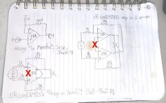
Not quite so.Attachment with op-amp equivalents and various stains
The upper right hand drawing has the inverting inputs connected together to nowhere.
The lower left assumes an inverting and non-inverting input, which does not suit the design.
There is no regular equivalent in opamps actually, not in 'split mode' either.
You're absolutly right!It bears some resemblance to Hiraga, an IPS followed by CFP CE OPS, all symmetrical/complementary, but that's about it.
But as soon as the input stage is modified to a differential, a double inverter 'intertwined' configuration will keep the circuit unconditionally stable.
I wish that was true...every complementary symmetrical circuit design ... starts and stops smoothly
The acronym is Citizen124032 (due to the reversed number). I'm not at home currently.You might visit the Citizen...
Attachments
Citizen124032,I wish that was true...
as you certainly know, my statement is true.
That doesn't matter, because I don't want to visit you either.The acronym is Citizen124032 (due to the reversed number). I'm not at home currently.
#
For goodness sake, I would like to repeat my suggestion:
Why don't you build your idea first, a test setup is quickly done, as well as a few test measurements - and then we could review your idea in a new thread.
HBt.
@dkfan9
Please don't let Citizen124032 lead you up the garden path and confuse you.
Perhaps you should read through the discussion thread linked above, then Citizen124032's objection will disappear into thin air.
Somehow I knew that someone would say something negative about your sketches.
Good night.
Please don't let Citizen124032 lead you up the garden path and confuse you.
Perhaps you should read through the discussion thread linked above, then Citizen124032's objection will disappear into thin air.
Somehow I knew that someone would say something negative about your sketches.
Good night.
Dear Citizen124032,
why do you believe that your circuit idea is superior to all other concepts?
Could you please explain this superiority in detail?
That would be wonderful, because your apodictic postulates are the cause of the disharmony. You may even post your simulation results and files here - or in a separate thread.
As is well known, we can never solve the questions of faith satisfactorily because each side wants to proselytize the other side - but we could technically dismantle your construct and describe it correctly.
The attitude that 'I can and know everything better' is becoming more and more disturbing to me. As already said, I'm happy for you if your amplifier works and meets all your wishes in terms of sound and artistry.
Bye,
HBt.
Instead of throwing things over the hedge (I'm not native english, but I'm sure you'll understand), I've been busy for several years now to develop an Hiraga 'on steroids', balanced and bridged, solid twice output based upon the 8W version, delivering 30+W running at 4 x 1.5Adc in the totem poles. Run through a zillion simulations now, no pole compensation needed, by surprise (huh???), phase flat from dc to >100k. The Hiraga design outperforms anything actually.
I dare no to post this as it is not prooven in my opinion, and never build. Only a setup is made, and all layout consideritions went overboard in the process. The diff pair is on handwidth distance, drivers and finals are 'tombola selected' counterparts 1943/5200. Everything is running warm, near hot.
Once settled (starting up / shutting down,), a modulation (the signal to be amplfied) seems insignificant...
Now that we know the development idea better, we can analyze it in a targeted manner:
4 times 1.5A equals 6A -> Iq = 6A / 2, i.e. three amps per (entire) output stage.
The power loss in idle state is therefore 3A * 12.96V, approximately 39W per Q33,Q34 & Q43,Q44.
This enormous power loss must be absorbed as thermal energy and dissipated to the environment, the room air, by means of convection.
In total 4*39W = 156W as heating - and there are still a whole handful of other losses missing here.
#
I am attaching the data sheets.
A friendly comment,
we do not use the term "totem pole" for your classic push-pull output stage - the usage here is completely wrong.
Attachments
Last edited:
I checked out the thread a few hours after you posted the link. Indeed, the I/O and feedback topology is identical, despite the differing internals.Nelson Pass offer from the year 2003
SUSY
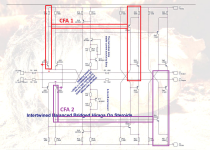
The top right does not have the inverting inputs connected to nowhere, it has them connected to each other. The negative inputs on a CFA are connected via a low impedance to differential ground. The two op-amps are just a way of drawing an LTP with differential outs followed by another inverting stage, with or without gain. If you look at NP's amp in the thread hbt posted, R0 turns the two independent CFA IPS into a differential pair. R0 is split into two resistors in your amp, the internal emitter resistance of Q21/Q23 and Q22/Q24. Any linear amplifier circuit can be drawn as an op-amp. I've attached an annotation of your amp with the 2 CFAs blocked off and inputs marked (the complementary side for each is part of each as well but not blocked off for legibility).Not quite so.
The upper right hand drawing has the inverting inputs connected together to nowhere.
The lower left assumes an inverting and non-inverting input, which does not suit the design.
There is no regular equivalent in opamps actually, not in 'split mode' either.
You're absolutly right!
But as soon as the input stage is modified to a differential, a double inverter 'intertwined' configuration will keep the circuit unconditionally stable.
As for the bottom left drawing, see figure 2 of the attached PDF app note on FDAs. Your amp eschews the cascode for additional gain, opting instead for a common emitter Sziklai OPS. Mark-up of fig 2 to show your variant as FDA attached. You used + and - yourself in your drawing. Of course, either one could be considered + or - and neither path internally inverts, but the point of an op-amp equivalent isn't to represent the internals but represent an amplifying device and its external terminals.
I do think it's an interesting design and would be interested to hear more about results of sims and additional performance details.
Attachments

delivering 30+W running at 4 x 1.5Adc in the totem poles.
Could it be that you wanted to express something else, namely Q+Q+Q+Q = 4Q and used the variable Q=1.5A?
Let's take a look at the class A operation:
(1/2) * (1.5A)^2 * 8Ohm = 9W
This fits perfectly with the rails of +15Vdc and -15Vdc.
Now we bridge and calculate the theoretically possible u_peak.
30V-(2*3V) = 24Vp
(24Vp)^2 / 8Ohm = 72Wp which corresponds to 36W in our class A concept.
The quiescent current must now be doubled, otherwise we switch to AB operation.
In short:
sqrt(2) * sqrt(36W/8Ohm) or also sqrt(72Wp/8Ohm) equals 3 amps.
Now we know that the Iq per branch or output stage must be 3A, unfortunately you have somehow concealed this fact. This cannot be due to the translation AI.
Last edited:
- Home
- Amplifiers
- Solid State
- Questions of faith - reflections on your own taste, thoughts about right or wrong!