Hi Olaf.
Can you share only PCB without parts in pdf, please? I would like to try your version with two pairs of transistors on output.
Regards.
Can you share only PCB without parts in pdf, please? I would like to try your version with two pairs of transistors on output.
Regards.
Have fun.
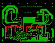
I will test a version with 1 pair of 2N2922. Hope it will be a nice compact modul.
(Picture is layout work in progress ;-)
regards
Olaf
Nice work, you can see in post #508 my old compact modul,
Regards
Hi Apex,
thanks. I will post pictures.
Can the amp work with +-36V DC?
regards
Olaf
Yes it can work with +/-36V without changes.
...for the compact version - not tested.
regards
Nice work and very fast 🙂
Regards
how to build same amplifier using 1 pair of 2n3055 pless replay with cercuit chenges
Use +/-30vdc rail voltage and you can use BD139/140 instead MJE340/350, BD241C/242C instead MJ15030/15031.

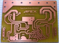
Prototype is ready. The sound is as good as expected. PCB needs some replacements, some cosmetics and nice heatsink. Then should be ok 😉.
regards
Olaf
Nice work,
Regards
Olaf,
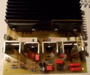
you have the output devices fixed to a fin of the heatsink.
This is not a good way to cool.
You should have the outputs fixed to the backplate of the heatsink.
The fins and the backplate of the heatsink should be vertical for best cooling.
you have the output devices fixed to a fin of the heatsink.
This is not a good way to cool.
You should have the outputs fixed to the backplate of the heatsink.
The fins and the backplate of the heatsink should be vertical for best cooling.
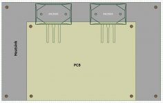
The devices are not in a good place to dissipate heat.
They would be much better cooled in the devices are located about 40% up from the bottom of the vertical backplate. And the fins must be vertical.
Locating as you have shown will leave the devices and the top edge of the heatsink quite hot. The bottom edge and much of the middle of the heatsink will remain quite cool in comparison. This wastes much of the dissipation capability of the heatsink.
Thanku but i want detail circuit digram using 2n3055. and how many wtts of output on using -/+ 30 v dc 5A pleass replay soon i am bigibar in amplifier desining
+-30Vdc will sag to maybe around +-27Vdc when driving full power to a test resistor.
The voltage lost through the amplifier could be very approximately 3Vdrop when delivery that full power to the test load.
That leaves your maximum output voltage @ ~24Vpk.
Pmax = Vpk^2 / Rload / 2.
I predict your maximum power for a +-30Vdc supply as ~ 36W into 8r0
These sums are simple. I expect you to never ask this question again !
- Home
- Amplifiers
- Solid State
- QUASI Amplifier for Beginners